MX-G500
1-12
Prior to performing the following procedure, remove
the CD tray.
Detach the belt from the pulley on the upper side of
the CD changer unit (Do not stain the belt with
grease).
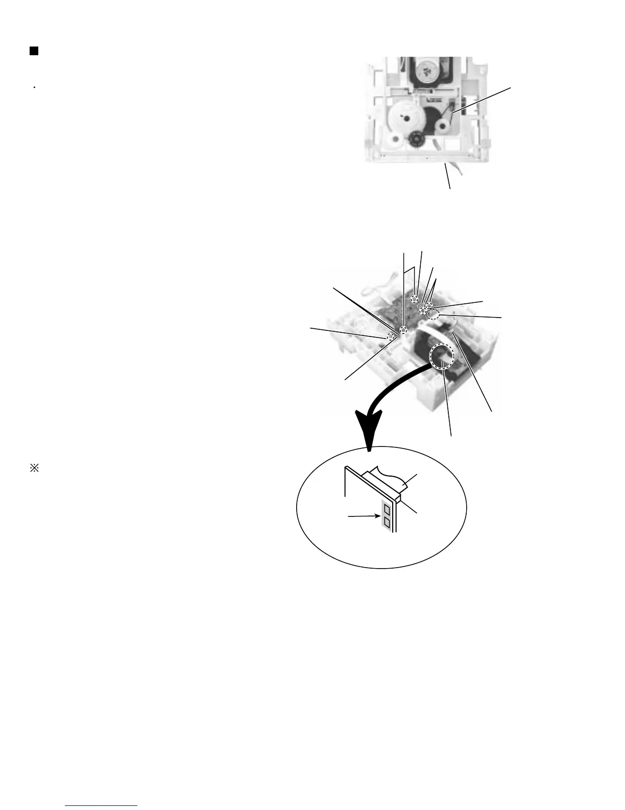
Disconnect the card wire from the pickup unit
connector on the under side of the CD changer unit.
Attention : Solder is put up before the card wire is
removed from the pick-up unit
connector on the CD mechanism
assembly.
(When the card wire is removed without
putting up solder, the CD pick-up unit
assembly might destroy.)
Disconnect the motor wire harness from connector
on the CD servo board.
Remove the screw C attaching the switch board and
release the two tabs e attaching the switch board
outward and detach the switch board.
Remove the two screws D attaching the CD servo
board and . First release the two tabs f and two tabs
g attaching the CD servo board motor to raise the
CD servo board slightly, then release the CD servo
board.
If the tabs f and g are hard to release, it is
recommendable to unsolder the two soldered parts
on the motor terminal of the CD servo board.
1.
2.
3.
4.
5.
Removing the belt, the CD servo board
and the switch board (See Fig.9 and 10)
Soldering
Card wire
Picup unit
connector
Fig.10
Fig.9
Belt
CD changer unit
D
CD servo board
Tabs g
Tabs f
Soldered parts
Motor
Switch board
C
CW3
Tabs e
CD mechanism board
motor connecter
Pickup unit connector
 Loading...