MX-G500
1-6
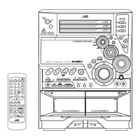
Prior to performing the following procedure, remove
the metal cover and the CD changer unit.
Disconnect the card wire from the connector FCW3
on the main board.
Disconnect the harness from the connector JCW1,
JCW2 and HCW3 on the main board.
Remove the two screws E attaching the front panel
assembly to both sides of the body.
Remove the screw F attaching the earth terminal
extending from the cassette mechanism assembly.
Remove the screw G attaching the main board to
front panel assembly.
Remove the screw H attaching the front panel
assembly to the bottom of the body.
Release the two joints1 and two joints2, and detach
the front panel assembly toward the front.
1.
2.
3.
4.
5.
6.
7.
Removing the front panel assembly
(See Fig.8 to 10)
Fig.6
Fig.7
Fig.5
RCW6
CD servo board
CD changer unit
Main board
CW107
CW105
Rear panel
C
D
(both sides)
Rear panel
CD changer unit
Front panel
assembly
Fig.8
Fig.9
Main board
Amp. board
FCW3
JCW2
JCW1
HCW3
ACW1
ACW2
Front panel
assembly
Joint1
(both sides)
E
(both sides)
Joint1
(both sides)
E
(both sides)
F(fixing the earth wire)
Front panel
assembly
G
Main board
 Loading...