MX-G500
1-7
Prior to performing the following procedure, remove
the metal cover and the CD changer unit.
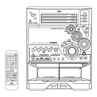
Disconnect the card wire from the connector ACW1
and the harness from the connector ACW2 on the
amp. board.
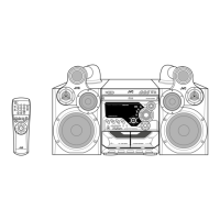
Remove the four screws I attaching the heat sink
cover to the rear panel. Remove the heat sink cover.
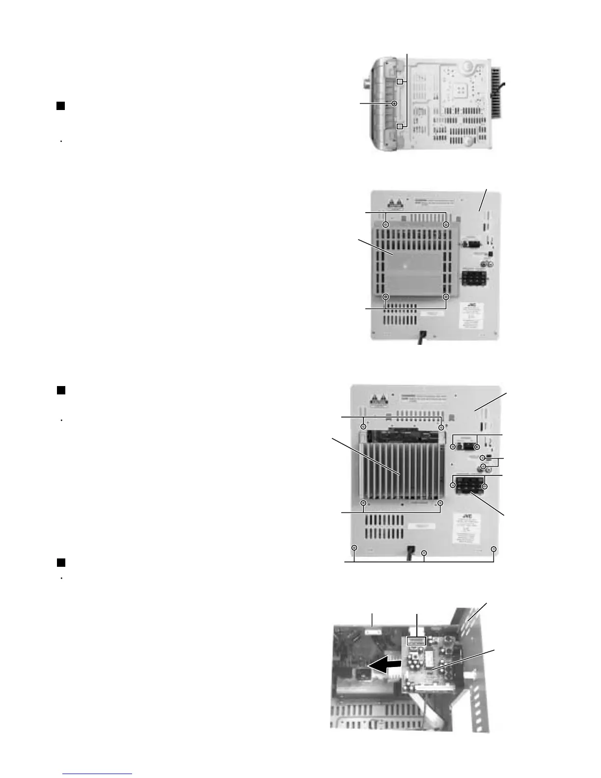
Remove the four screws J attaching the heat sink
and two screws K attaching the speaker terminal to
the rear panel.
After moving the heat sink upward, remove the
claws. Then pull out the heat sink & amp. board
inward.
1.
2.
3.
4.
Removing the heat sink & amp. board
(See Fig.8, 11 and 12)
Prior to performing the following procedure, remove
the metal cover.
Disconnect the card wire from the connector CON01
on the tuner board.
Remove the two screws L attaching the tuner board
to the rear panel.
1.
2.
Removing the tuner board
(See Fig.12 and 13)
Prior to performing the following procedure, remove
the metal cover, CD changer unit, heat sink & amp.
board and tuner board.
Remove the two screws M and three screws N
attaching the rear panel.
1.
Removing the rear panel (See Fig.12)
Fig.10
H
Joint2
(Bottom side)
Fig.11
Rear panel
Heat sink
cover
I
I
Fig.12
Fig.13
Heat sink
Speaker
terminal
K
M
N
L
Main board
Rear panel
Tuner board
CON01
J
J
Rear panel
 Loading...