Do you have a question about the JVC MX-J10 and is the answer not in the manual?
Safety guidelines specific to laser-based products.
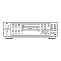
General safety and operational warnings for the unit.
Lists all supplied accessories with the system.
Instructions for installing batteries in the remote control.
Guide on how to connect the FM antenna to the unit.
Guide on how to connect the AM antenna to the unit.
Procedures for powering the system on and off.
How to control the audio output volume level.
Explanation of available sound effect modes.
Steps for tuning into radio stations manually or automatically.
How to store favorite radio stations for quick access.
Basic operation for playing a CD.
Methods to choose specific tracks or sections on a CD.
Basic procedure for playing a cassette tape.
How to enable playback of both sides of a cassette.
Procedure for setting the system's internal clock.
Instructions for setting automatic power-on/off timers.
Guidelines for handling and cleaning compact discs.
Tips for proper storage and handling of cassette tapes.
Steps to remove the main unit's outer metal cover.
Lists required test equipment for calibration.
Important considerations before starting adjustment procedures.
Procedure to verify and adjust head angle settings.
Procedure to verify and adjust tape speed accuracy.
Reference values for confirming double tape speed performance.
Reference values for forward/reverse speed difference.
Steps to adjust recording bias current for optimal performance.
Electrical test values for confirming system functionality.
Procedure for replacing the laser pickup unit.
Details and pin functions for the BA15218F operational amplifier IC.
Details and pin functions for the TC4053BP analog switch IC.
Details and pin functions for the BA6897FPW 4-channel driver IC.
Block diagram illustrating the CD player circuitry.
Detailed schematic for the cassette deck's electronic components.
Schematic diagram for the CD player's servo and amplifier circuits.
Layout of the system control printed circuit board.
Layout of the headphone jack printed circuit board.
Layout of the power supply printed circuit board.
Visual breakdown of the entire system with part numbers.
Detailed parts list for the cassette mechanism assembly.
Detailed parts list for the CD changer mechanism assembly.
List of electrical components used in the system.
Lists packaging materials and included accessories.
| Playable Media | CD, CD-R, CD-RW |
|---|---|
| MP3 Playback | Yes |
| Frequency Response | 20 Hz - 20 kHz |
| Signal-to-Noise Ratio | 80 dB |
| Tuner | FM/AM |
| Weight | 4.5 kg |
| DAC | 1-bit |
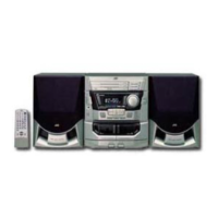
| Type | Mini Hi-Fi System |