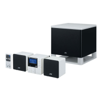
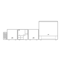
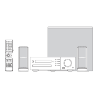
NX-MD1R/NX-MD1
1-13
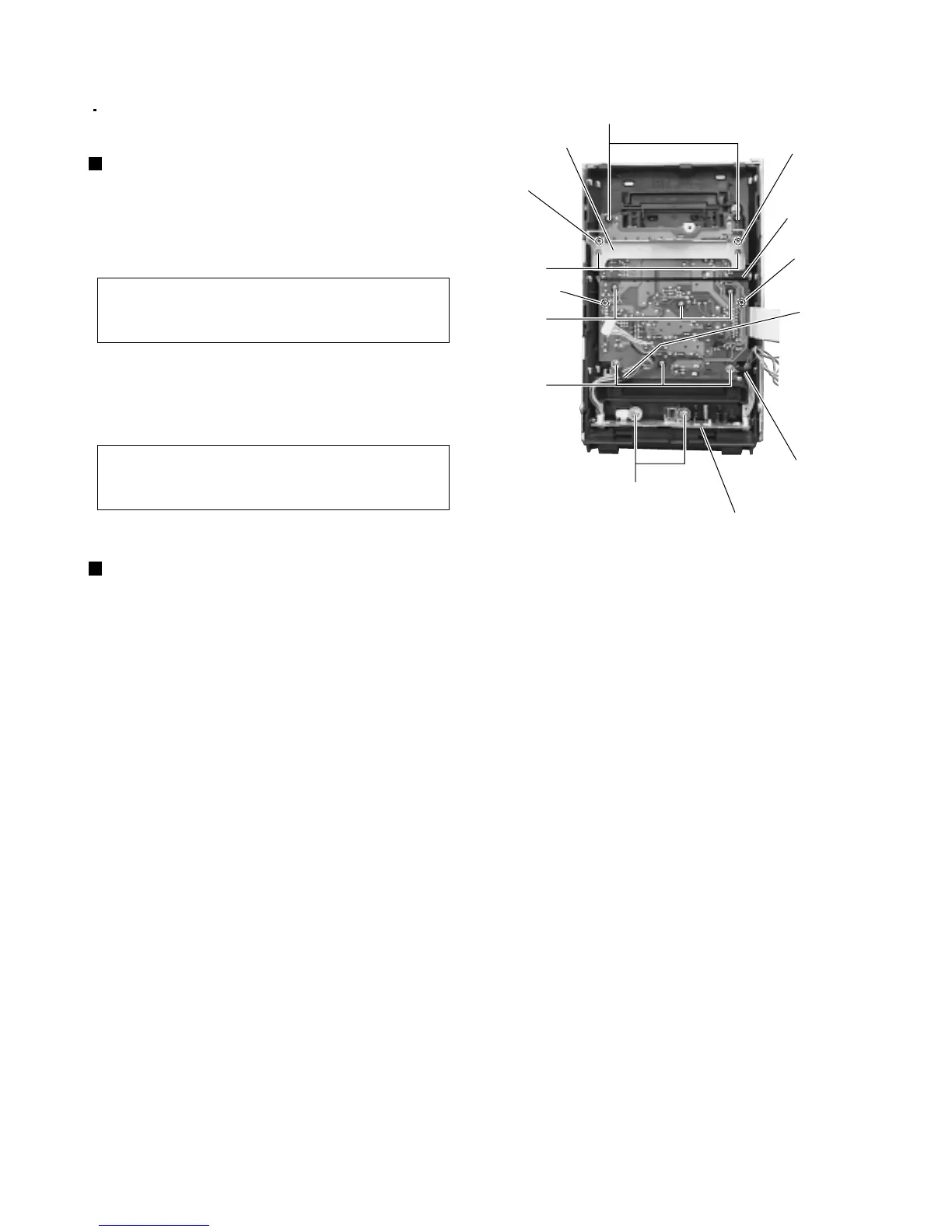
Removing the front board (See Fig.16)
1.
2.
3.
4.
Remove the two screws Y attaching the MD
bracket.
Remove the MD bracket.
(Caution) When assembling, fit the rib of the front
panel into the location hole g on the MD
bracket before attaching it.
Remove the eight screws Z attaching the front
board.
Remove the front board.
(Caution) When assembling, fit the rib of the front
panel into the location hole h on the
front board before attaching it.
Prior to performing the following procedure, remove
the front panel assembly.
<Front panel assembly section>
Fig.16
Removing head phone & USB board
(See Fig.16)
1.
2.
3.
Remove the wire from two wire holders i.
Remove the two screws AA attaching the head
phone & USB board.
Remove the head phone & USB board.
Z
Z
Y
Z
Wire holder i
AA
Wire holder i
Front board
Head phone & USB board
Location hole g
Location hole h
Location hole h
Location hole g
MD bracket

 Loading...