(No.MB707<Rev.002>)1-7
SECTION 2
SPECIFIC SERVICE INSTRUCTIONS
This service manual does not describe SPECIFIC SERVICE INSTRUCTIONS.
SECTION 3
DISASSEMBLY
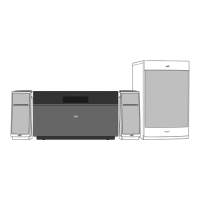
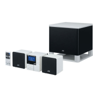
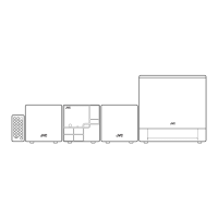
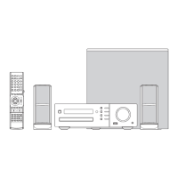
3.1 Main body (Used figure were NX-T10E)
3.1.1 Removing the DVD door
(1) Connect the Main unit and Subwoofer.
(2) Power to ON and then open the DVD door.
(3) Slid to front side and pull up the DVD door.
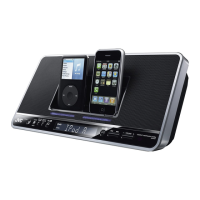
3.1.2 Removing the Top cabinet (See Fig.1, 2, 3, 4)
(1) Remove the six screws A attaching the Top cabinet. (See
Fig.1)
(2) Disconnect the card wire from DVD MPEG board connect-
ed to connector CNC5
of the Connect board. (See Fig.1)
Fig.1
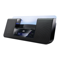
(3) Remove the four screws B attaching the Top cabinet. (See
Fig.2)
Fig.2
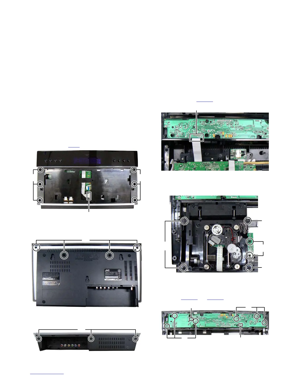
(4) Remove the three screws C attaching the Top cabinet.
(See Fig.3)
Fig.3
(5) Disconnect the card wire from DVD MPEG board connect-
ed to connector CON401
of the Display board. (See Fig.4)
Fig.4
3.1.3 Removing the DVD mechanism (See Fig.5)
(1) Remove the four screws D attaching the DVD mechanism.
(2) Remove the two screws E attaching the Connect board.
Fig.5
3.1.4 Removing the DVD mechanism (See Fig.6)
(1) Remove the six screws F attaching the Display board.
(2) Disconnect the card wire from Key board connected to con-
nectors CON402
and CON403 of the Display board.
Fig.6
AA
CNC5
B
C
CON401
D
D
D
E
CON403
CON402
F
F
 Loading...