EasyManua.ls Logo

JVC PC-V55 B - Page 11

JVC PC-V55 B
29 pages
Print Icon
To Next Page IconTo Next Page
To Previous Page IconTo Previous Page
Loading...
PC-V55
B/E/G
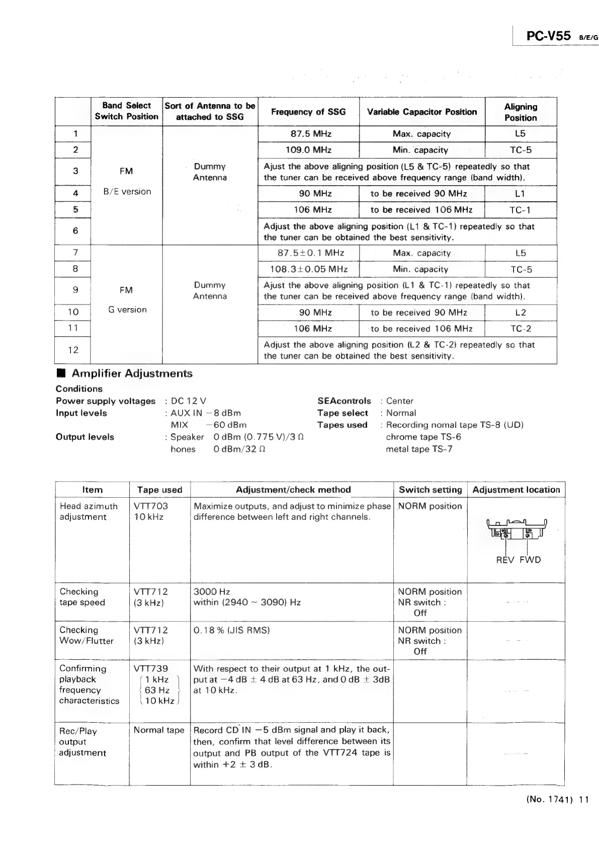
Band
Select
Switch
Position
Sort
of
Antenna
to
be
attached
to
SSG
Aligning
Position
Frequency
of
SSG
Variable
Capacitor
Position
2
109.0
MHz
Min.
capacity
TC-5
3
EM
Dummy
Ajust
the
above
aligning
position
(L5
&
TC-5)
repeatedly
so
that
Antenna
the
tuner
can
be
received
above
frequency
range
(band
width).
4
B/E
version
|
90
MHz
to
be
received
90
MHz
5
106
MHz
to
be
received
106
MHz
TC-1
6
Adjust
the
above
aligning
position
(L1
&
TC-1)
repeatedly
so
that
|
the
tuner
can
be
obtained
the
best
sensitivity.
7
87.5+0.1
MHz
Max.
capacity
L5
+
8
108.340.05MHz
|
Min.
capacity
TC-5
9
EM
Dummy
Ajust
the
above
aligning
position
(L1
&
TC-1)
repeatedly
so
that
Antenna
the
tuner
can
be
received
above
frequency
range
(band
width).
10
G
version
90
MHz
to
be
received
90
MHz
L2
11
106
MHz
to
be
received
106
MHz
TC-2
12
Adjust
the
above
aligning
position
(L2
&
TC-2)
repeatedly
so
that
the
tuner
can
be
obtained
the
best
sensitivity.
@
Amplifier
Adjustments
Conditions
Power
supply
voltages
:DC12V
SEAcontrols_
:
Center
Input
levels
:
AUX
IN
—8dBm
Tape
select
:
Normal
MIX
—60
dBm
Tapes
used:
Recording
nomal
tape
TS-8
(UD)
Output
levels
:
Speaker
OdBm
(0.775
V)/3
2
chrome
tape
TS-6
hones
0
dBm/32
0
metal
tape
TS-7
Item
Tape
used
Adjustment/check
method
Switch
setting
|
Adjustment
location
Head
azimuth
VTT703
Maximize
outputs,
and
adjust
to
minimize
phase
|
NORM
position
adjustment
10
kHz
difference
between
left
and
right
channels.
REV
FWD
uf
Checking
VTT712
3000
Hz
NORM
position
tape
speed
(3
kHz)
within
(2940
~
3090)
Hz
NR
switch
:
Off
Checking
VTT712
0.18
%
(JIS
RMS)
NORM
position
Wow/Flutter
(3
kHz)
NR
switch
:
7
Off
|
Confirming
VTT739
With
respect
to
their
output
at
1
kHz,
the
out-
playback
j
1
kHz
|
put
at
—4dB
+
4dB
at
63
Hz,
andOdB
+
3dB
frequency
63
Hz
at
10
kHz.
characteristics
|
10
kHz
|
Rec/Play
output
adjustment
Normal
tape
i
Record
CD
IN
—5
dBm
signal
and
play
it
back,
then,
confirm
that
level
difference
between
its
output
and
PB
output
of
the
VTT724
tape
is
“
=
within
+2
+
3
dB.
(No.
1741)
11