Do you have a question about the JVC PC-5 L and is the answer not in the manual?
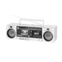
Complete stereo component system in a single box with 5 units.
Lists unique capabilities like Auto-Scanning, Metal Tape compatibility, and 4-way power supply.
Details track system, motors, heads, frequency response, S/N ratio, and input/output specs.
Details power output, frequency response, S/N ratio, tone control, and input/output specs.
Lists FM, AM, LW frequency ranges, sensitivity, selectivity, and separation.
Details speaker type, units, impedance, frequency response, and input power.
Covers power sources, consumption, and overall unit dimensions and weight.
Instructions on connecting pin cords and power cords before switching on.
Guidance on correct speaker cord connection for optimal stereo performance.
Details FM/SW antenna setup and turntable/remote control connections.
Instructions for removing and mounting speaker joint fixtures.
Steps for attaching the carrying handle and mounting the rear cover.
Guide on using the unit as a portable deck with different power sources.
Identifies controls and indicators on the tuner and amplifier units.
Identifies controls and indicators on the cassette deck and speaker units.
Diagram showing the location of major components within the tuner unit.
Diagram showing the location of major components within the amplifier unit.
Diagram showing the location of major components within the cassette deck unit.
Step-by-step guide for disassembling the tuner unit.
Step-by-step guide for disassembling the amplifier unit.
Step-by-step guide for disassembling the cassette deck unit.
Detailed steps for removing mechanical components of the cassette deck.
Instructions for removing the cassette door and engaging dial cord.
Guide for disassembling the speaker unit.
Illustrates the functional blocks and signal flow of the tuner circuit.
Illustrates the functional blocks and signal flow of the amplifier circuit.
Diagrams for recording, playback, and mechanical control circuits of the cassette deck.
Procedures for adjusting record/playback head position, erase head height, and motor speed.
Detailed steps for adjusting playback level, frequency response, and recording level.
Steps for aligning IF, RF, and MPX circuits for optimal tuner performance.
Detailed schematic of the PC-T5 tuner's electronic circuitry.
Detailed schematic of the PC-A5 amplifier's electronic circuitry.
Schematics for cassette amplifier and mechanical control circuits.
Diagram showing internal wiring for the PC-T5 tuner unit.
Diagram showing internal wiring for the PC-A5 amplifier unit.
Diagrams for cassette amplifier and mechanical control wiring.
Comprehensive list of enclosure and electrical parts for the tuner.
Comprehensive list of enclosure and electrical parts for the amplifier.
Comprehensive list of enclosure, mechanical, and button assembly parts.
List of enclosure and electrical parts for the speaker unit.
Diagrams for mounting and connecting the portable component system.
Lists standard accessories provided with the unit.
Instructions on how to pack the main unit and speakers.
Details a change in the power supply circuit and front panel character.
| Country | Japan |
|---|---|
| Manufacturer | JVC |
| Model | PC-5 L |
| FM Frequency Range | 87.5 - 108 MHz |
| Power Source | AC/DC |
| Tape Deck | Cassette |
| Tuner | AM/FM |
| AM Frequency Range | 530 - 1, 605 kHz |
| Signal-to-Noise Ratio | 50dB |
| Power Supply | DC 12V |
| Speakers | 2-way speaker system (12cm woofer, 5cm tweeter) |