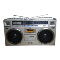
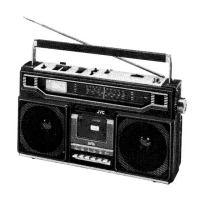
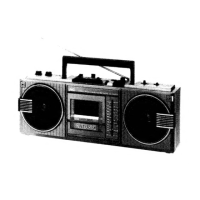
The JVC RC-545L/LB is a portable stereo cassette recorder with a 4-band radio tuner, designed for both playback and recording. This service manual provides comprehensive details on its specifications, parts, assembly, and maintenance procedures.
Function Description
The device integrates a multi-band radio tuner (FM, SW, MW, LW) with a stereo cassette recorder. It allows users to listen to radio broadcasts across various frequencies and to record audio onto cassette tapes, either from the radio or via external microphone inputs. Stereo playback is supported through built-in speakers or headphones. The cassette mechanism includes features for playback, recording, fast forward, rewind, cue, review, and pause, making it a versatile audio device for its time.
Important Technical Specifications
Dimensions:
- Height: 24.1 cm (9-1/2")
- Width: 42.4 cm (16-3/4")
- Depth: 11.4 cm (4-1/2")
Weight:
- Approximately 4.5 kg (9.9 lbs) with batteries.
Tuner Section:
- Frequency Ranges:
- FM: 88~108 MHz
- SW: 6~18 MHz
- MW: 540~1600 kHz
- LW: 150~350 kHz
Recorder Section:
- Tape Speed: 4.8 cm/s (1-7/8 ips)
- Track System: 4-track 2-channel stereo
- Recording System: AC Bias
- Erasing System: DC Erasing
- S/N Ratio: More than 40 dB at 1 kHz
- Fast Forward Time: Within 90 seconds (C-60 cassette)
- Rewinding Time: Within 90 seconds (C-60 cassette)
- Wow & Flutter: 0.14% (WRMS)
Amplifier Section:
- Speakers: 12 cm (5") x 2, 3.2 Ω impedance
- Power Output:
- Maximum: 5.4 W (2.7 W + 2.7 W) (DC)
- At 10% THD: 4 W (2 W + 2 W) (DC)
- Input Jacks:
- MIC x 2 (0.8 mV, low impedance)
- Output Jacks:
- Ext. Speaker x 2 (3.2~8 Ω)
- Headphones x 1 (8 Ω)
- Input/Output Jack: DIN
- Power Consumption:
- 12 W (RC-545L)
- 9.5 W (RC-545LB)
Semiconductors:
- ICs: 5 + 2 (Microphone)
- Transistors: 10 + 2 (Motor governor)
- Diodes: 14
Power Source:
- DC: 9 V, 6 "R20", "U2" cells or equivalent
- AC: 110/220/240 V, 50/60 Hz
Usage Features
The RC-545L/LB features separate controls for volume, balance, and tone, allowing users to customize their listening experience. A fine-tuning knob is provided for precise radio station selection. The stereo cassette recorder offers standard functions like play, record, fast forward, and rewind, along with "Cue" and "Review" mechanisms for easy navigation within a tape. A PAUSE button allows for temporary interruption of recording or playback. The device's portability is enhanced by its ability to operate on both AC power and batteries.
Maintenance Features
The service manual outlines detailed procedures for disassembly, replacement of parts, and various alignments to ensure optimal performance.
Disassembly & Replacement:
- Rear Cabinet: Instructions for removing the battery cover, screws, and disconnecting antenna and power supply connectors.
- Tuner Section: Steps for removing tuning knobs, disconnecting connectors, and accessing the tuner chassis. Special note on engaging the pointer with the pointer holder during reassembly.
- Amplifier Circuit Board: Guidance on removing control knobs, disconnecting connectors, and unscrewing the board.
- Amplifier Section (with Cassette Mechanism): Detailed steps for disconnecting connectors and screws, and opening the cassette case to disengage the internal mechanism.
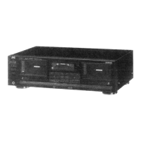
- Cassette Mechanism: Instructions for removing the amplifier section, unscrewing the mechanism, and desoldering wires from the motor, heads, and leaf switch. The manual notes that the cassette mechanism is similar to RC-525 and RC-323 models, referring to their service manuals for component parts.
- Jack Board: Procedures for removing the amplifier circuit board and unscrewing the jack board.
- Power Supply Section: Simple instructions for removing two screws.
Alignment Procedures:
- Tuner Alignment:
- AM IF & RF Alignment: Step-by-step instructions using a Signal Generator (SSG) for adjusting IF and RF coils and variable capacitors across MW, LW, and SW bands.
- FM IF & Discriminator Alignment: Procedures using a sweep generator and oscilloscope to align IF and discriminator circuits for peak and S-curve waveforms.
- FM RF Alignment: Instructions for aligning FM RF coils and variable capacitors using a 75Ω terminal, modulated signal, and SSG.
- FM MPX Alignment: Regular and simplified methods for adjusting the variable resistor VR1 to achieve the correct frequency (19 kHz ± 100 Hz) for stereo indication.
- Adjusting Recording Bias: Procedures for connecting a frequency counter and V.T.V.M. to test points to adjust the oscillator coil (L301) for 68 kHz bias frequency and variable resistors (VR101, VR201) for 4.5 mV bias current.
- Adjusting Head Azimuth: Regular and simplified methods using a dual channel oscilloscope or V.T.V.M. and a test cassette to adjust the head angle for maximum output and in-phase signals.
- How to Fit Dial Cord: Detailed instructions for fitting the tetoron dial cord, including length, diameter, and steps for routing and adjusting the pointer.
- Adjustment of Cassette Mechanism:
- Play Timing: Adjusting the clearance between the pinch roller arm and head base stopper (0.2-0.3 mm) by bending the pinch roller arm. Also, ensuring take-up idler and pinch roller turn simultaneously.
- Cue & Review Mechanism: Adjusting timing to ensure take-up reel disk stops correctly after pinch roller action.
- Pause Timing: Adjusting the pinch roller arm to ensure the take-up reel and pinch roller stop simultaneously when the PAUSE button is pressed.
- Thrust of Flywheel: Adjusting the thrust screw to maintain a clearance of 0.1-0.4 mm between the flywheel shaft and thrust screw.
- Location of Heads: Specifying precise positioning for play/record and erase heads.
- Torque: Providing torque specifications for PLAY (40-70 g.cm), FF (more than 60 g.cm), and REWIND (more than 60 g.cm), with a note to change the take-up reel disk if torque is out of limits.
The manual also includes detailed parts lists for the tuner circuit board, amplifier circuit board, cassette mechanism, connector circuit board, LED circuit board, and power supply circuit board, along with exploded views for easy identification of components. Asterisked parts indicate "NEW PARTS," while others are "CURRENT PARTS," advising technicians to check inventory before ordering. Parts marked with a triangle are critical for safety assurance and must be replaced with specified parts.