Do you have a question about the JVC RC-W410 and is the answer not in the manual?
Details essential safety measures, procedures, and critical warnings for product operation and servicing.
Details of buttons and switches for cassette deck operation on both decks A and B.
Identifies front panel controls like tuner, volume, equalizer, switches, and indicators.
Procedure for removing the rear cabinet assembly, including wire disconnection and connector removal.
Steps for detaching the speaker unit and hyper-bass sound box, specifying screws and wire clamps.
Instructions for removing the tuner, main, power amplifier, synthesizer/LCD boards, and mechanism assembly.
Guidance on removing operation buttons and the power transformer/supply board assembly.
Lists required equipment and measurement conditions, detailing cassette performance checks and calibration.
Specifies conditions, adjustment points, and connection details for tuner section calibration.
Covers calibration for AM IF, FM IF, and LW/MW RF tracking adjustments.
Detailed procedures for fine-tuning FM RF tracking and optimizing FM multiplex signal separation.
Detailed circuit schematic illustrating the tuner section, including all components and connections.
Detailed circuit schematic illustrating the amplifier section, including audio and power supply circuits.
Diagram showing the physical layout of components on the Main P.C. Board (sections #1-500).
Diagram illustrating the placement of components on the Main P.C. Board (sections #501 onwards).
Diagram showing the physical layout of components on the Tuner Board (sections #1-500).
Diagrams showing component layouts for Tuner Board (#501~) and Power Supply Board.
A comprehensive list of all parts used on the Tuner Board, including part numbers and descriptions.
Diagram illustrating the physical layout of components on the Synthesizer/LCD Board.
A comprehensive list of all parts used on the Synthesizer/LCD Board, including part numbers and descriptions.
| Tuner | AM/FM |
|---|---|
| Brand | JVC |
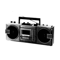
| Model | RC-W410 |
| Type | Cassette Player |
| Power Source | AC/Battery |
| Battery Type | D batteries |
| Speaker | 2 Speakers |