Do you have a question about the JVC RC-660 L and is the answer not in the manual?
Information on safety marks and precautions for component replacement.
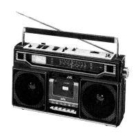
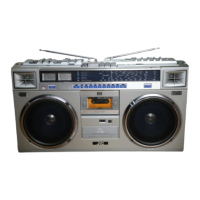
Identifies and labels various controls on the unit's front and side panels.
Illustrates the placement of major internal components like P.W. boards and speakers.
Steps for removing the rear cabinet and DIN jack assembly.
Procedures for removing the tuner, power supply, and amplifier boards.
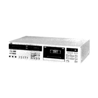
Steps for removing the cassette mechanism and speakers.
Illustrates the process of engaging the dial cord for tuning.
Details checks and adjustments for the cassette mechanism after replacement.
Procedures for electrical adjustments in the amplifier section.
Steps for FM RF alignment specific to RC-660L/LB/LS models.
Steps for FM RF alignment specific to RC-660LD models.
Steps for FM RF alignment specific to RC-660LE models.
Diagram showing alignment component locations for tuning.
Detailed schematic diagram for the tuner section of RC-660L/LB.
Detailed schematic diagram for the tuner section of RC-660LD.
Detailed schematic diagram for the tuner section of RC-660LE.
Detailed schematic diagram for the tuner section of RC-660LS.
Detailed schematic diagram for the amplifier section of RC-660L/LB.
Detailed schematic diagram for the amplifier section of RC-660LD/LE/LS.
Block diagram illustrating the playback signal path.
Block diagram illustrating the record signal path.
List of parts for the Tuner P.W. Board of RC-660L/LB/LS models.
List of parts for the Tuner P.W. Board of RC-660LD/LE/LS models.
Diagram of the Amplifier P.W. Board for RC-660L/LB.
Parts list for the VMW1070-00XA Amplifier P.W. Board assembly.
Parts list for the VMW1070-00XB Power Supply P.W. Board assembly.
Parts list for the VMW1070-00XC/D E.C. MIC P.W. Board assembly.
Parts list for the RC-660LD/LE Amplifier P.W. Board.
Parts list for the DIN Jack P.W. Board of RC-660LD/LE/LS.
Diagram of the Amplifier P.W. Board for RC-660LD/LE/LS.
Diagram illustrating wiring connections between components.
List of mechanical components from ref. no. 1 to 74.
List of mechanical components from ref. no. 75 to 110.
Visual representation of mechanism component layout and numbering.
Diagram illustrating the assembly of enclosure parts.
List of parts for the enclosure assembly.
Illustration of the packing process and components.
List of parts included in the packing.
List of included accessories and their remarks.
| Brand | JVC |
|---|---|
| Model | RC-660 L |
| Signal-to-Noise Ratio | 45 dB |
| Total Harmonic Distortion | 1.5% |
| Type | Radio Recorder |
| Power Source | AC/DC |
| Radio | FM, AM, LW |
| Weight | 5.5 kg |
| Frequency Response | 50 Hz - 12 kHz |