Do you have a question about the JVC RX-750VBK and is the answer not in the manual?
Procedure for checking electrical shock hazards after assembly.
Explains the POWER button and the STAND BY indicator function.
Details SEA PRESET and SEA LEVEL adjustment controls.
Covers audio inputs, sound processing, tape dubbing, balance, mute, volume, and phono cartridge settings.
Covers remote power control and standby mode.
Covers remote power control and standby mode.
Details output power, distortion, sensitivity, frequency response, and S.E.A. specs.
Step-by-step guides for removing front panel, tuner board, bracket, and transistors.
Procedures for checking pre-amplifier and power amplifier PC boards.
Covers discriminator distortion, FM tuning, sensitivity, muting, and signal strength.
Covers stereo distortion and separation adjustments.
Covers AM tuning, idling current, and power supply switching circuit adjustments.
Provides guidelines for safely handling LCD panels.
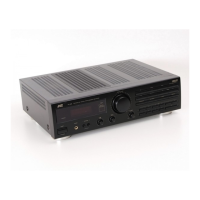
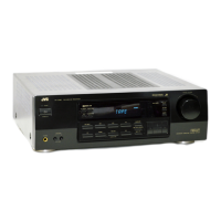
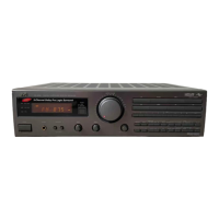
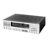
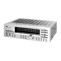
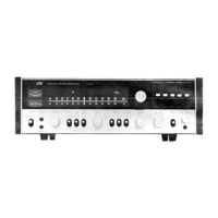
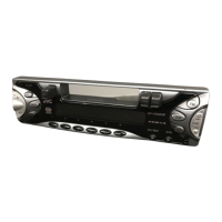
Identifies major components on the unit's front, top, and rear views.
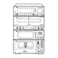
Shows an exploded view and lists parts.
Lists parts for various PC board assemblies.
Provides an overall block diagram of the system.
Shows detailed schematics for Tuner, Logic, Pre-Amplifier, and Power Amplifier sections.
| Power Output | 100 watts per channel into 8Ω (stereo) |
|---|---|
| Channels | 2 |
| Frequency Response | 10Hz to 50kHz |
| Total Harmonic Distortion | 0.007% |
| Input sensitivity (MM) | 2.5 mV |
| Input sensitivity (line) | 200mV |
| Signal to noise ratio (line) | 90 dB |
| Input Impedance | 47 kΩ |
| Tuning range | FM |
| Video Connections | Composite video input/output |
| Power Output (alternative) | 100 W per channel (8 ohms) |
| Dimensions (alternative) | 430 x 150 x 320 mm |
| Weight (alternative) | 8 kg |
| Speaker load impedance | 8 ohms |
| Speaker Impedance | 8 ohms |