FS-SD1000R
1-8
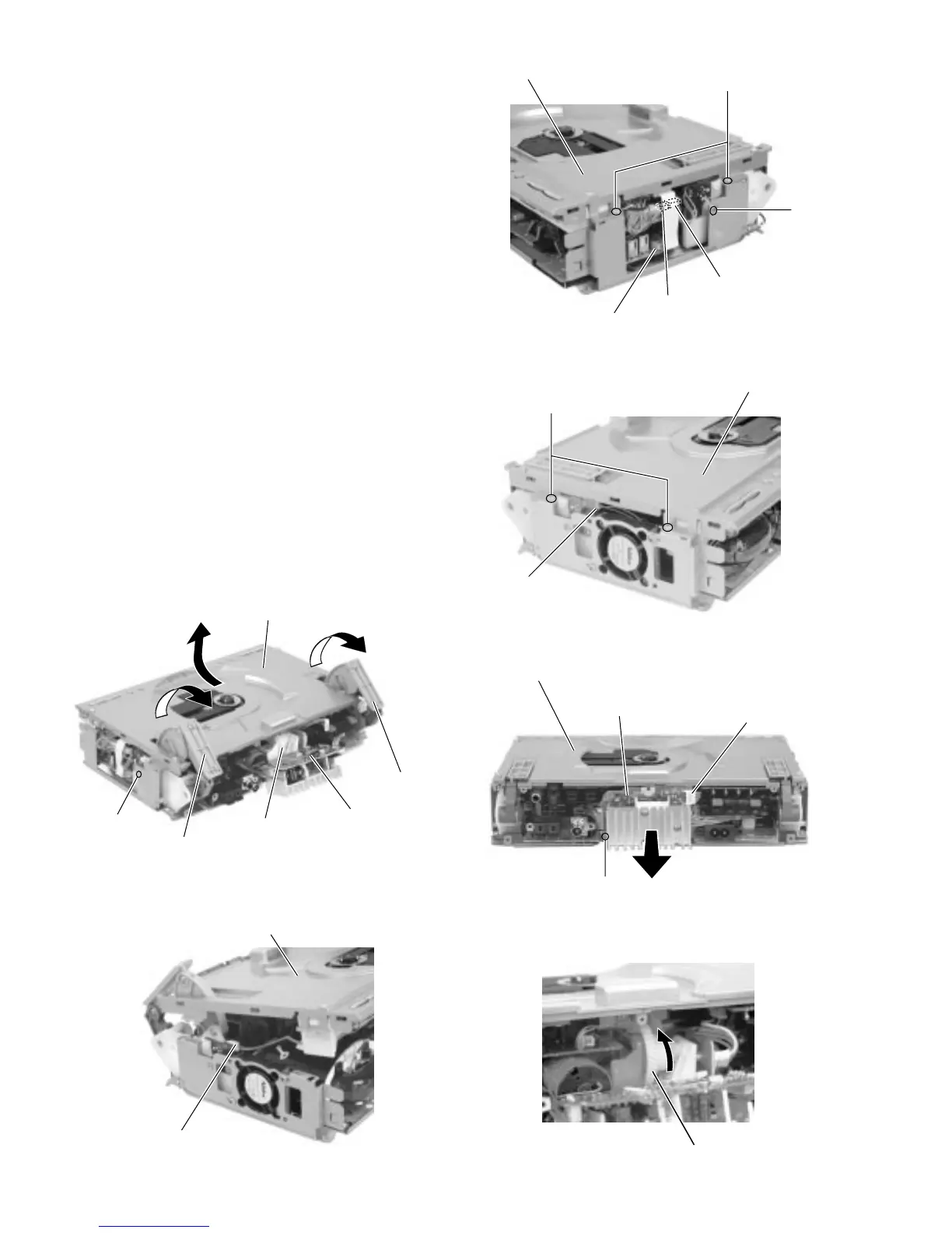
Remove the screw G attaching the power amplifier
board on the back of the body. Disconnect the wire
from connector CN301 and pull the power amplifier
board fully outward.
Raise the right and left door arms by turning the gear
a in the rear of the power amplifier board.
After the CD mechanism base assembly is detached
from the door arms, pull the CD mechanism base
assembly toward the front and disconnect the wire
from connector CN804 on the left side of the door
arm board.
Pull out the CD mechanism base assembly toward
the front.
3.
4.
5.
6.
Fig.9
Fig.10
Fig.11
F
I
CD mechanism base assembly
Main board
CN101
CN708
F
CD mechanism base assembly
CN804
CD mechanism base assembly
CN301
G
Power amplifier board
Fig.13
Gear a
Fig.12
Fig.14
CD mechanism base assembly
Power amplifier board
Door arm
Door arm
I
Gear a
CD mechanism base assembly
Door arm board (L)
CN804
CN705
 Loading...