(No.MB294)1-27
3.4 Speaker section
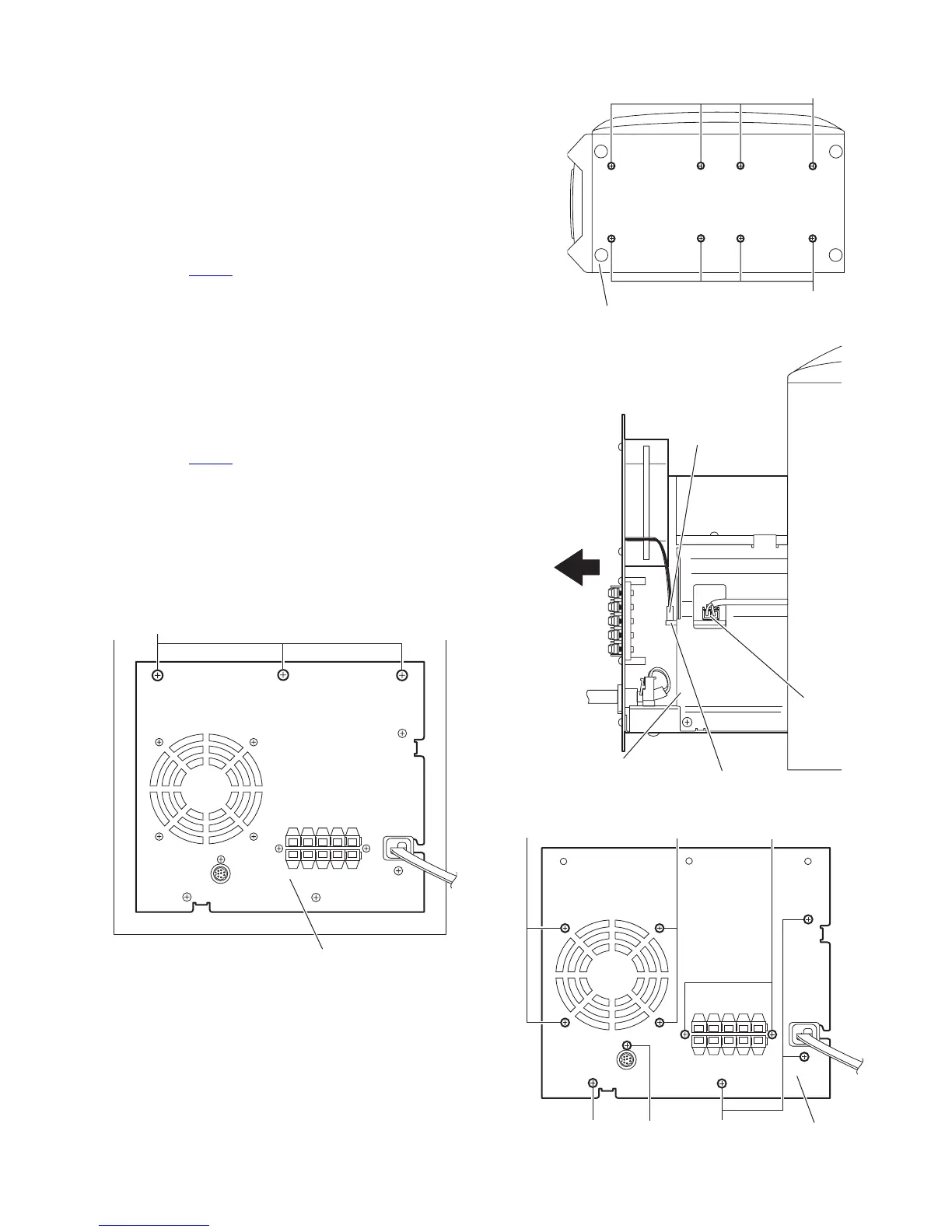
3.4.1 Removing the amplifier assembly
(See Figs.1 to 3)
(1) From the back side of the speaker main body, remove
three screws A attaching the amplifier assembly. (See
Fig.1)
(2) From the bottom side of the speaker main body, remove
the eight screws B attaching amplifier assembly. (See
Fig.2)
(3) From the top side of the speaker main body, move the am-
plifier assembly backward and disconnect the wire from the
connector CN204
on the amplifier board. (See Fig.3)
3.4.2 Removing the rear panel
(See Figs.3 and 4)
• Prior to performing the following procedure, remove the ampli-
fier assembly.
(1) From the back side of the amplifier assembly, remove the
four screws C, screw D and two screws E attaching the rear
panel. (See Fig.4)
(2) From the top side of the amplifier assembly, take out the
rear panel with fan motor, and disconnect the wire from the
connector CN202
on the amplifier board. (See Fig.3)
3.4.3 Removing the fan motor
(See Fig.4)
• Prior to performing the following procedures, remove the am-
plifier assembly and rear panel.
(1) From the front side of the rear panel, remove the four
screws F attaching the fan motor.
(2) Take out the fan motor.
Fig.1
Fig.2
Fig.3
Fig.4
Amplifier assembly
A
Speaker main body
B
B
CN204
Amplifier board
Amplifier assembly
CN202
Amplifier assembly
D
C
E
F
F
C
 Loading...