(No.MB294)1-29
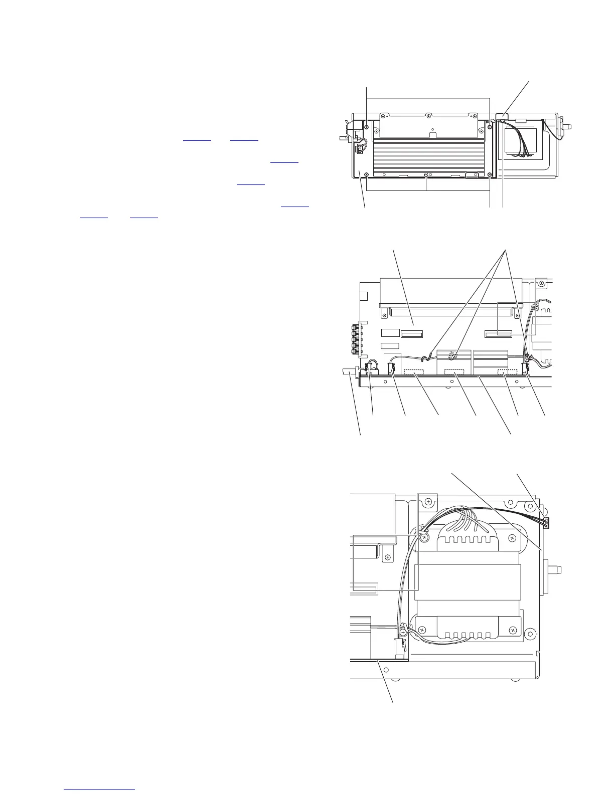
3.4.6 Removing the power board
(See Figs.7 to 9)
• Prior to performing the following procedures, remove the am-
plifier assembly, rear panel, heat sink bracket and amplifier
board.
(1) From the right side of the amplifier assembly, remove the
five screws J attaching the power board. (See Fig.7)
(2) From the top side of the amplifier assembly, disconnect the
wires from the connectors CN312
and CN321 on the power
board. (See Fig.8)
(3) Disconnect the power cord from the connector CN311
on
the power board, and take out the power cord. (See Fig.8)
(4) Disconnect the wire from the connector CN501
on the LED
board. (See Fig.9)
(5) Disconnect the power board from the connector CN301
,
CN302
and CN303 on the main board, and take out the
power board assembly from the amplifier assembly. (See
Fig.8)
Reference:
Remove the screw K attach the barrier as required. (See Fig.7)
Fig.7
Fig.8
Fig.9
Power board
Barrier
J
J
K
CN311
CN312
CN303 CN302 CN301
CN321
Power cord
Power board
Main board Wire clamps
Power board
LED board
CN501
 Loading...