1-30 (No.MB294)
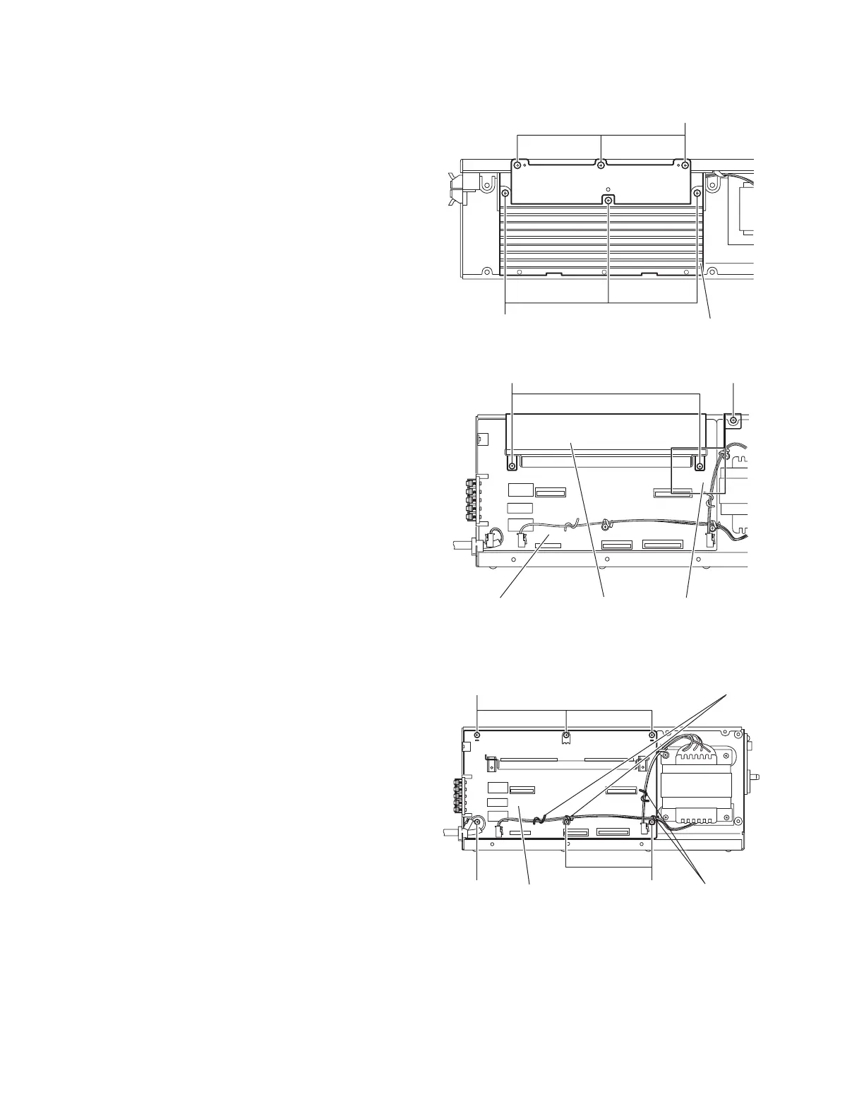
3.4.7 Removing the heat sink
(See Figs.10 and 11)
• Prior to performing the following procedures, remove the am-
plifier assembly, rear panel, heat sink bracket, amplifier board
and power board.
(1) From right side of the amplifier assembly, remove the three
screws L and three screws M attaching the heat sink. (See
Fig.10)
(2) From the top side of the amplifier assembly, remove the
two screws N attaching the heat sink to the main board.
(See Fig.11)
(3) Take out the heat sink.
Reference:
Remove the screw P attach the barrier as required.
Fig.10
Fig.11
3.4.8 Removing the main board
(See Fig.12)
• Prior to performing the following procedures, remove the am-
plifier assembly, rear panel, heat sink bracket, amplifier board,
power board and heat sink.
(1) From the top side of the amplifier assembly, remove the
wires from the wire clamps on the main board.
(2) Remove the three screws Q and two screws Q’ attaching
the main board.
(3) Take out the main board.
Reference:
• When attaching the main board, attach the screws Q’ with
wire clamps.
• After attaching the main board, bundle the wire by the wire
clamps.
Fig.12
Heat sink
M
L
N
P
Main board
Heat sink
Barrier
Wire clamps
Wire clamps
Q
Main boardQ
Q'
 Loading...