GUIDE TO REPAIR.
(Note: Models SX-W35L, SX-W35R, and SX-W35C have no individual parts to replace. The entire unit is replaced when repairs are necessary)
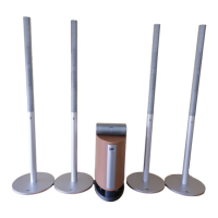
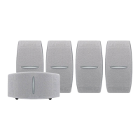
MODEL SX-W35W SUBWOOFER:
A. "Removing grille assembly"
1. Uft with even pressure the press-fit frame away from the grommet holes in the speaker cabinet.
A1."Replacing the grille assembly"
1. Insert new grille assembly into the grommet holes on the cabinet and press down using even pressure.
B. =Removing the woofer"
1. Unscrew the (4) screws holding down the woofer.
2. Remove the (4) wire clips from the woofer terminal, noting positive (blue & green) and negative (black & brown) wires.
B1 =Replacing the woofer
1. Attach the blue crossover wire to the (+) terminal, Side #1
2. Attach the black crossover wire to the (-) terminal, Side #1
3. Attach the green crossover wire to the (+) terminal, Side #2
4. Attach the browncrossover wire to the (-) terminal, Side #2
5. Screw down the woofer using (4) screws, pin hw scr #8x7.
C. =Removing the crossover"
1. Remove the woofer following steps outlined in "B" above.
2. Unscrew the (6) screws holding down the crossover.
3. Remove the crossover from the cabinet.
Cl. "Replacing the crossover"
1. Insert the crossover into the hole in the rear of the cabinet and screw down into position using (6) screws, pin hw scr 6x6
2. Attach the blue crossover wire to the (+) terminal of the woofer, side #1
3. Attach the black crossover wire to the (-) terminal of the woofer, side #1
4. Attach the green crossover wire to the (+) terminal of the woofer, side #2
5. Attach the brown crossover wire to the (+) terminal of the woofer, side #2
6. Screw the woofer back into position using (4) screws, pin hw scr #8x7
D1 ."Replacing the grey logo cavity =backing" strip"
1. Remove the old backing by prying up.
2. Press fit the new grey backing strip into the logo cavity on the grille frame, making sure the logo stud hole is towards the
bottom.
3. Pry up the top half and put a small amount of hot melt glue in the center of the strip, upper half, and press down into
place, making sure the glue does not overflow the sides.
E. =Replacing the logo"
1. Press the logo stud through the hole in the grey backing.
2. Use a nut driver and a 5mm socket to =push" pushnut (pin hw pnu t-sub) over the logo stud and lock the logo in place in
the grille frame.
PARTS LIST, MODELS SX-W35L, SX-W35R, SX-W35C
ITEM PART NUMBER PART NAME QTY DESCRIPTION
1
2
3
4
5
sp-asy-jsat-I Complete speaker 1 Left speaker
sp-asy-jsat-r Complete speaker 1 Right speaker
sp-asy-sat-c Complete speaker 1 Center speaker
pk-bag-sat Polybag 1
hw-bmp-jsatc Rubber =pad" 4 Foot/center ch
PARTS LIST, MODEL SX-W35W SUBWOOFER
ITEM PART NUMBER PART NAME QTY DESCRIPTION
1 hw-bmp-jsubh Rubber Bumper
2 hw-grom-orb Grommet
3 hw-pnut-sub Pushnut
4 hw-scr-#6x6 Screw
5 hw-scr-#8x7 Screw
.6 pk-bag-jsubh Polybag
7 sp-woo-jsubh Woofer
8 wo-jsubh-cab Cabinet
9 grf-jsubh Grille frame
10 Ibk-jsubh Grey back strip
11 Iog-subh Logo
,12 tuf-a- 1/2 Insulation
13 xov-jsubh Crossover
4
4
1
6
4
1
1
1
1
1
1
1
1
"Feet" for sub
Grille frame support
Logo support stud
Size 6 x 5/8"
Size 8 x 3/4"
8" DVC woofer
Wood cabinet
Adhesive strip
Logo with stud
Crossover with wires
 Loading...