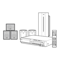
(No.MB511)1-13
3.1.4 Removing the audio & digital input board
(See Fig.6 and 9)
(1) Disconnect the card wire from connector CN102
of the au-
dio & digital input board. (See Fig.9)
(2) Disconnect the connector CN101
connecting the connec-
tion board. (See Fig.9)
(3) From the back side of main body, remove the one screw H
and one screw J attaching the audio & digital input board.
(See Fig.6)
(4) Move the audio & digital input board to front ward until dis-
engage position from the bracket board, and then take out
to up ward. (See Fig.9)
3.1.5 Removing the USB jack board
(See Fig.9)
(1) Remove the one screw K attaching the USB jack board.
(See Fig.9)
3.1.6 Removing the tuner pack
(See Fig.6 and 10)
(1) Disconnect the card wire from connector CN410
of the
main board. (See Fig.10)
(2) Remove the two screws L attaching the tuner pack. (See
Fig.6)
3.1.7 Removing the main board
(See Fig.6 and 11)
(1) Disconnect the card wires from connector CN401
, CN402,
CN403 and CN404 of the main board. (See Fig.11)
Reference:
This step is unnecessary if the DVD changer mechanism
assembly is removed previously.
(2) From back side of main body, remove the five screws M at-
taching the main board. (See Fig.6)
(3) Remove the three screws N attaching the main board. (See
Fig.11)
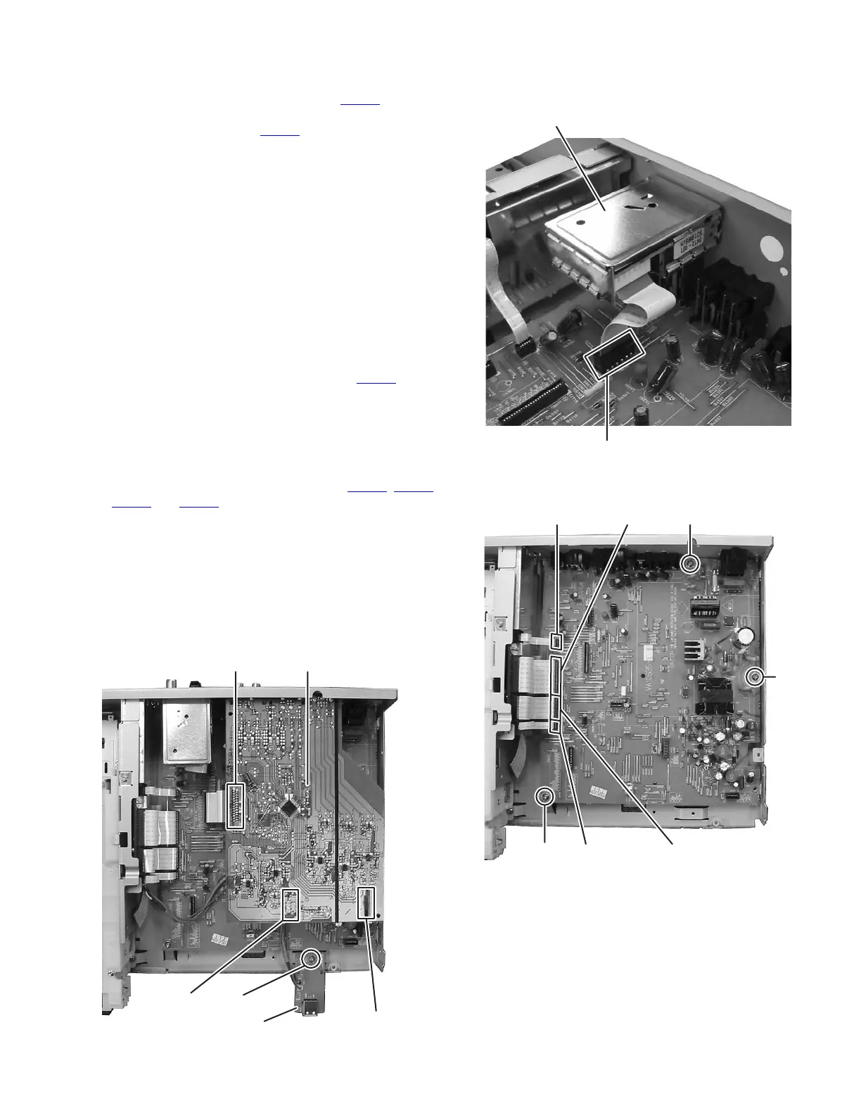
Fig.9
Fig.10
Fig.11
CN101
CN102
Audio & Digital input
board
Bracket board
USB jack board
K
Tuner pack
CN410
N
N
N
CN401 CN402
CN403CN404