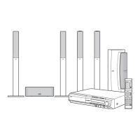
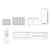
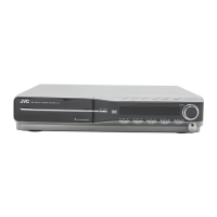
1-20 (No.MB570)
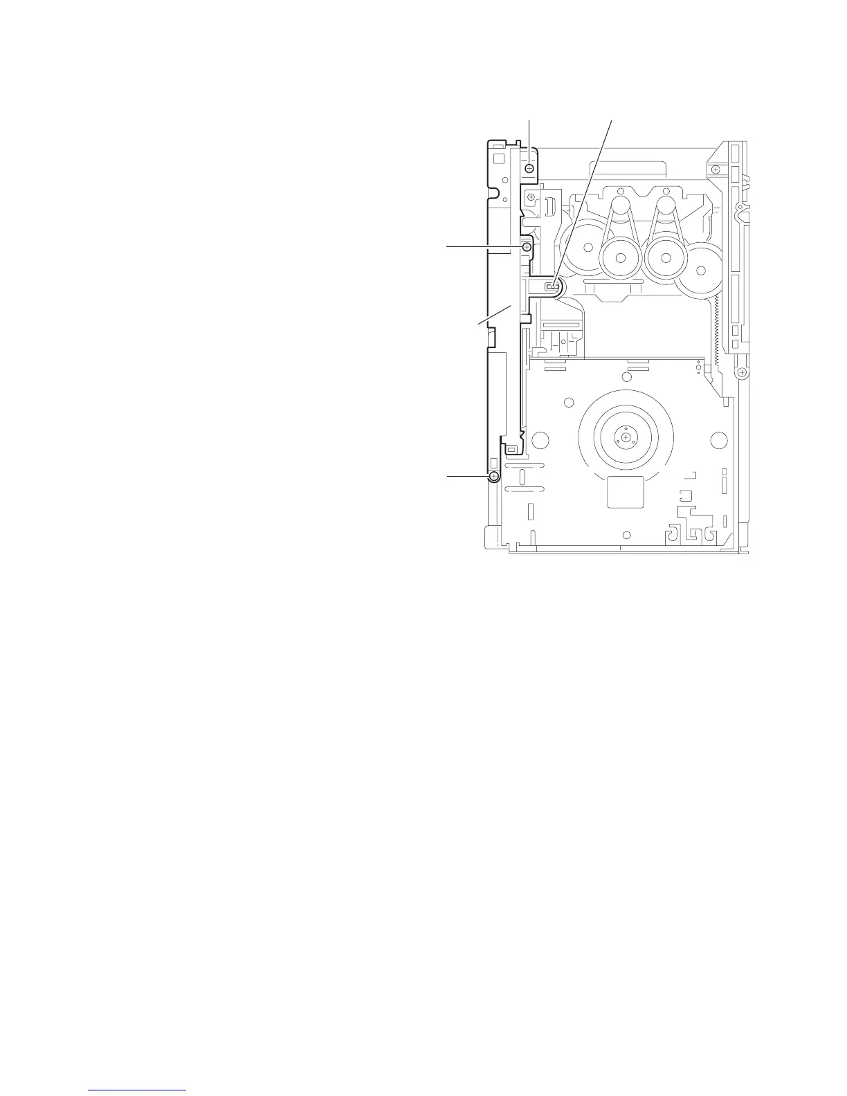
3.2.8 Removing the side (R) assembly
(See Fig.15 to 19)
(1) Remove the three screws L attaching the side (R) assem-
bly. (See Fig.15)
(2) Remove the spring attached to part g of the hook on the
right side of the body. (See Fig.16)
(3) Push and release the two tabs h of the gear cover through
the notches inside the side (R) assembly. Remove the gear
cover outward. (See Fig.17)
(4) From top of the body, turn the 1 gear clockwise to move the
elevator cam rearward. Move the two slots k and joint m of
the elevator cam as shown Fig.18 and remove the elevator
cam outward.
(5) Remove the three screws M and detach the side (R) up-
ward. (See Fig.19)
Caution:
When reattaching the side (R) assembly, make sure to fit the
shaft into the slot of the select lever.
Fig.15
M
Side (R)
assembly
M
Mh