31
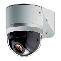
Machine ID Setting Switch
When controlling the system via a multi DROP system such
as RM-P2580, a machine ID will be attached to the system to
differentiate it from other connected cameras.
Match the machine ID with the [VIDEO INPUT] number of
RM-P2580.
Memo :
● For details on the Machine ID setting switch, please refer
to [Machine ID] (A Page 21).
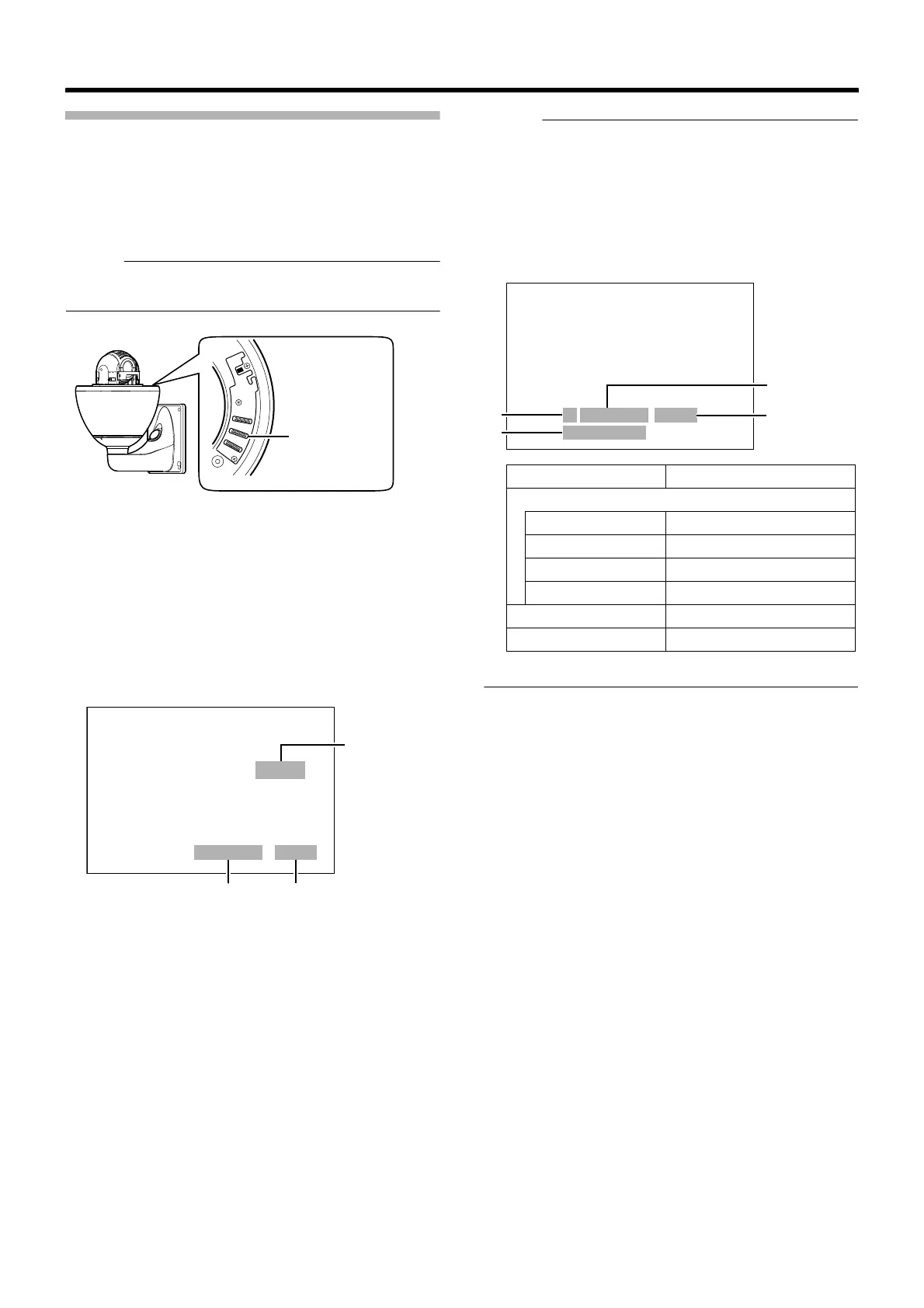
䡵 Machine ID Confirmation Procedures
1
Output the image of the camera to be checked on the
monitor
2 Turn on the power of the camera
● The camera initializes and the following screen is
displayed on the monitor.
3 Check the display on the monitor screen
A Confirm that ADUPLEXB is displayed
B Check that AID-LLB is displayed and LL is the correct
number
● They match the [VIDEO INPUT] number of RM-P2580.
● Otherwise, reset the machine ID.
C The indication changes depending on the switch2 setting
in the setting switches. (A Page 30)
● AONB B(100P)
● AOFFB B(256P)
Memo :
● When operating a system using the RM-P2580, several
cameras can be connected and used on one control
signal cable. Consequently, an incorrect switch setting on
just a single camera will cause the entire system to work
incorrectly.
● The following screen appears when Pelco protocol is
used. Check to ensure that the display items are
consistent with the system.
Machine ID
Setting Switch
>>
INITIAL PROCESS (100P)
<<
PAN : - - I - -
TILT : - - I - -
PROTOCOL DUPLEX : ID-01
A B
C
䡵 When JVC protocol is used
>>
INITIAL PROCESS
<<
PAN : - - I - -
TILT : - - I - -
>>
PROTOCOL
<<
P DUPLEX ID-01
2400,N,8,1
A
B
C
D
A Protocol Name P (Pelco Protocol)
B Comunication Configuration
Baud Rate 1200, 2400, 4800, 9600
Parity N, O, E
Data Bit 8
Stop Bit 1
C Machine ID ID-00 to ID-255
D Topology Duplex