1-10
UX-A52R
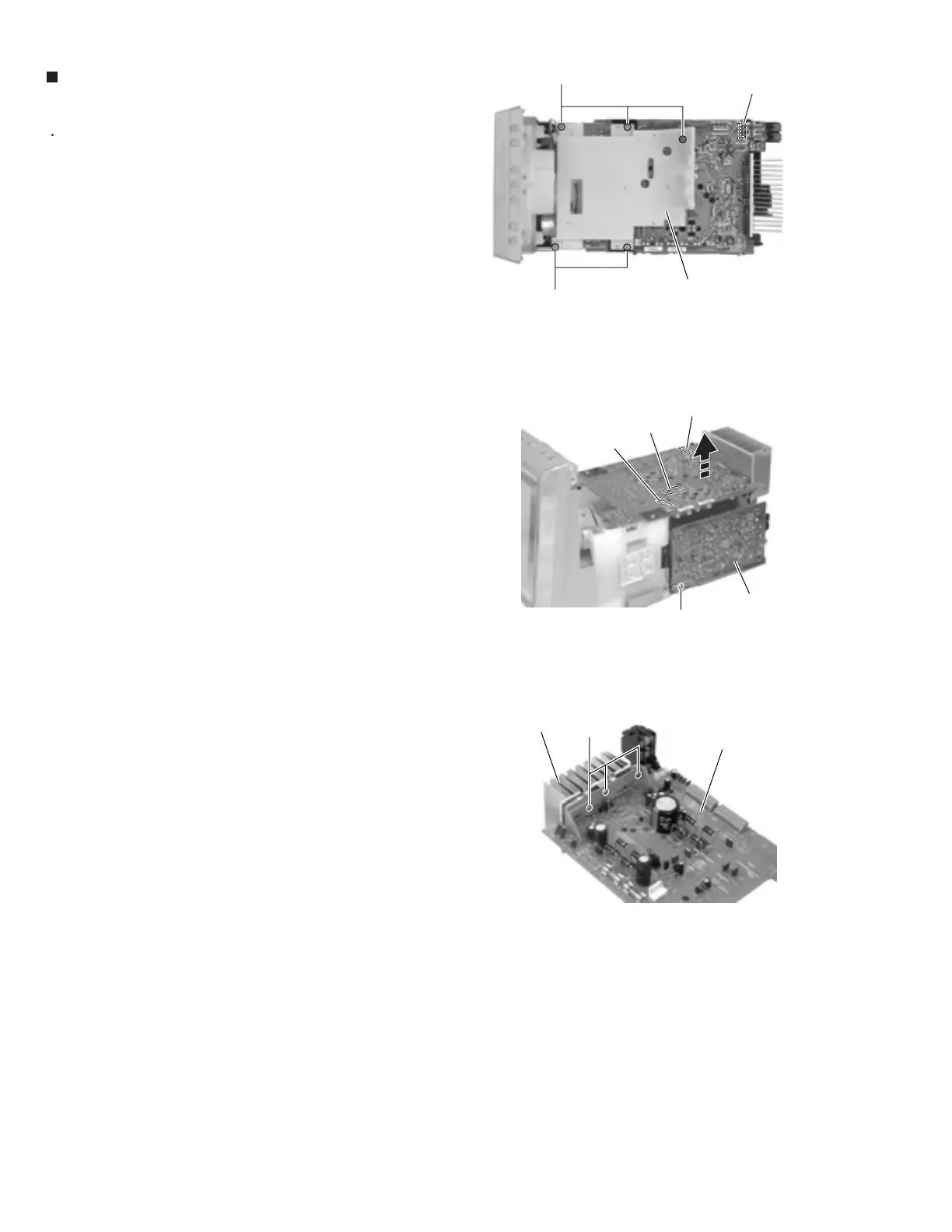
Prior to performing the following procedure, remove
the rear cover, the side panels, the top panel, the
cassette mechanism assembly section and and the
system control board.
Disconnect the wire from connector CN804 on the
main board.
Remove the five screws H attaching the cassette
mechanism bracket.
Remove the screw G attaching the grounding
terminal extending from the main board.
Disconnect connector CN805 on the main board
from the AC jack board while pulling out it. Remove
the main board in the direction of the arrow and
disconnect the wire from connector CN803 on the
reverse side of the main board.
Remove the three screws I attaching the heat sink
on the reverse side of the main board.
1.
2.
3.
4.
5.
Removing the main board / the heat sink
(See Fig.15 to 17)
Fig.15
Fig.16
Fig.17
H
Main board
CN805
CN803
Tuner board
Heat sink
I
H
G
Main board
CN804
Cassette mechanism bracket
Main board
CN804
 Loading...


