1-11
UX-A52R
Prior to performing the following procedure, remove
the rear cover, the side panels, the top panel, the
cassette mechanism assembly section, the system
control board and the main board / the tuner board.
Disconnect the wire from connector CN809 on the
AC jack board.
Remove the screw J and screw K attaching the AC
jack board.
1.
2.
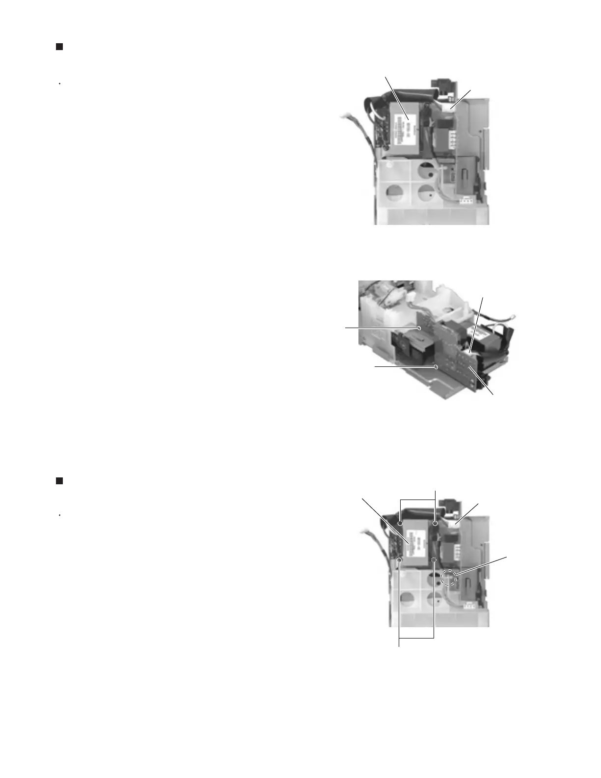
Removing the AC jack board
(See Fig.18 and 19)
Prior to performing the following procedure, remove
the rear cover, the side panels, the top panel, the
cassette mechanism assembly section, the system
control board and the main board.
Disconnect the wire from connector CN809 on the
AC jack board.
Cut off the band setting the wire on the CD
mechanism cover.
Remove the four screws L attaching the power
transformer assembly.
1.
2.
3.
Removing the power transformer
assembly (See Fig.20)
Fig.18
AC jack board
CN809
Power transformer assembly
Fig.19
AC jack board
CN809
K
J
Fig.20
L
AC jack board
CN809
Power transformer
assembly
Band
L
 Loading...


