1-12
UX-A52R
Prior to performing the following procedure, remove
the rear cover, the side panels, the top panel, the
cassette mechanism assembly section, the system
control board, the front panel assembly section, the
main board / the tuner board and the AC jack board.
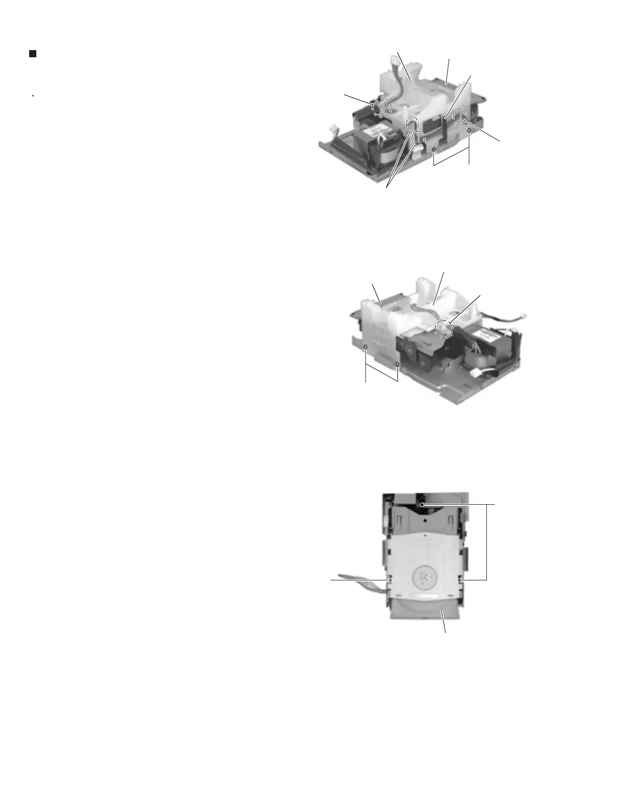
Cut off the band setting the wire on the CD
mechanism cover.
Release the wire extending from the headphone jack
board from the spacer and the three notches of the
CD mechanism cover on the left side of the body.
Remove the four screws M on the left and right side
of the CD mechanism cover. Then remove the CD
mechanism cover upward.
Remove the three screws N attaching the CD
mechanism assembly.
1.
2.
3.
4.
Removing the CD mechanism assembly
(See Fig.21 to 23)
Fig.21
Fig.22
Fig.23
CD mechanism cover
CD mechanism cover
Band
Band
CD mechanism assembly
CD mechanism assembly
CD mechanism assembly
Notches
Notch
M
M
N
N
Spacer
 Loading...


