1-13
UX-A52R
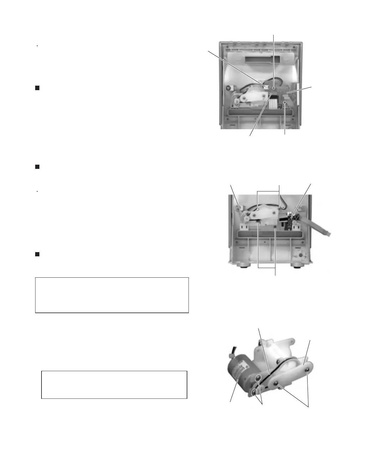
Prior to performing the following procedure, remove
the relay board.
Remove the four screws P attaching the drive motor
assembly.
1.
<Front panel assembly section>
Removing the drive motor assembly
(See Fig.25)
Disconnect the wire from connector CN906, CN907
and the card wire from CN908 on the relay board
respectively.
Remove the two screws O.
Prior to performing the following procedure, remove
the rear cover, the side panels, the top panel, the
system control board and the front panel assembly
section.
1.
2.
Removing the relay board (See Fig. 24)
Remove the two screws Q attaching the plate.
Remove the belt from the two pulleys.
Remove the two screws R attaching the drive motor.
1.
2.
3.
Removing the belt and the drive motor
(See Fig.26)
The belt and the drive motor can be
removed respectively without removing the
drive motor assembly from the front panel
section.
REFERENCE:
When removing the drive motor only,
remove the belt from the drive motor
pulleys in advance.
REFERENCE:
Fig.24
Fig.25
Fig.26
O
Relay board
CN906
O
CN907
CN908
P
P
Door switch board
Drive motor assembly
Drive motor
Belt
Plate
Q
R
 Loading...


