1-14
UX-A52R
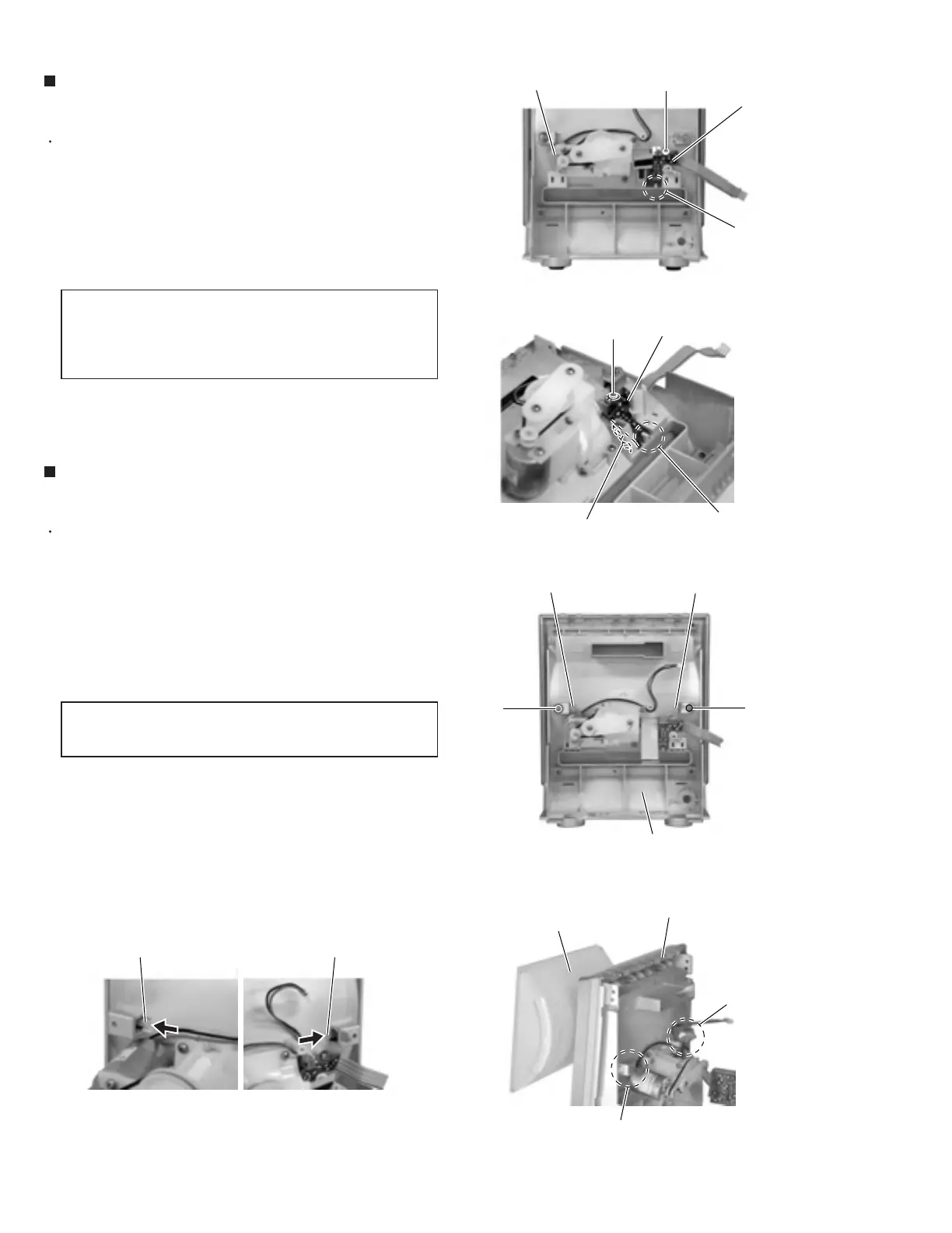
Prior to performing the following procedure, remove
the relay board.
Loosen the screw S attaching the door switch.
Remove the door switch board while releasing it from
the joint e.
1.
2.
Prior to performing the following procedure, remove
the relay board.
Loosen the two screws T attaching the lock lever.
Push the part f of the lock lever in the direction of
the arrow as shown in Fig.30-1 / 30-2 and disengage
the LCD section from the front panel assembly.
1.
2.
Removing the door switch board
(See Fig.27 and 28)
Removing the LCD section
(See Fig.29 to 31)
When reattaching the door switch board,
fit it to the joint e and check the
operating state of the switch before
tightening the screw S.
CAUTION:
Because the LCD may come off, hold it
when loosening the screws T.
CAUTION:
Fig.27
Fig.28
Fig.29
Fig.30-1 Fig.30-2
Fig.31
S
Joint e
Joint e
Joint f
Door switch board
Door switch board
S
T
T
Lock lever f Lock lever f
Lock lever
Lock lever
LCD section
Switch section
Front panel assembly
Front panel assembly
Drive motor assembly
Joint f
 Loading...


