1-19
UX-A52R
Reference:The mechanism board can be removed
without removal of the TRAMECHA
assembly.
Note:Before disconnecting the flexible wire coming
from the pickup from the connector, be sure to
solder its shorting round.
If the flexible wire is connected without
soldering, it may cause breakdown of the
pickup.
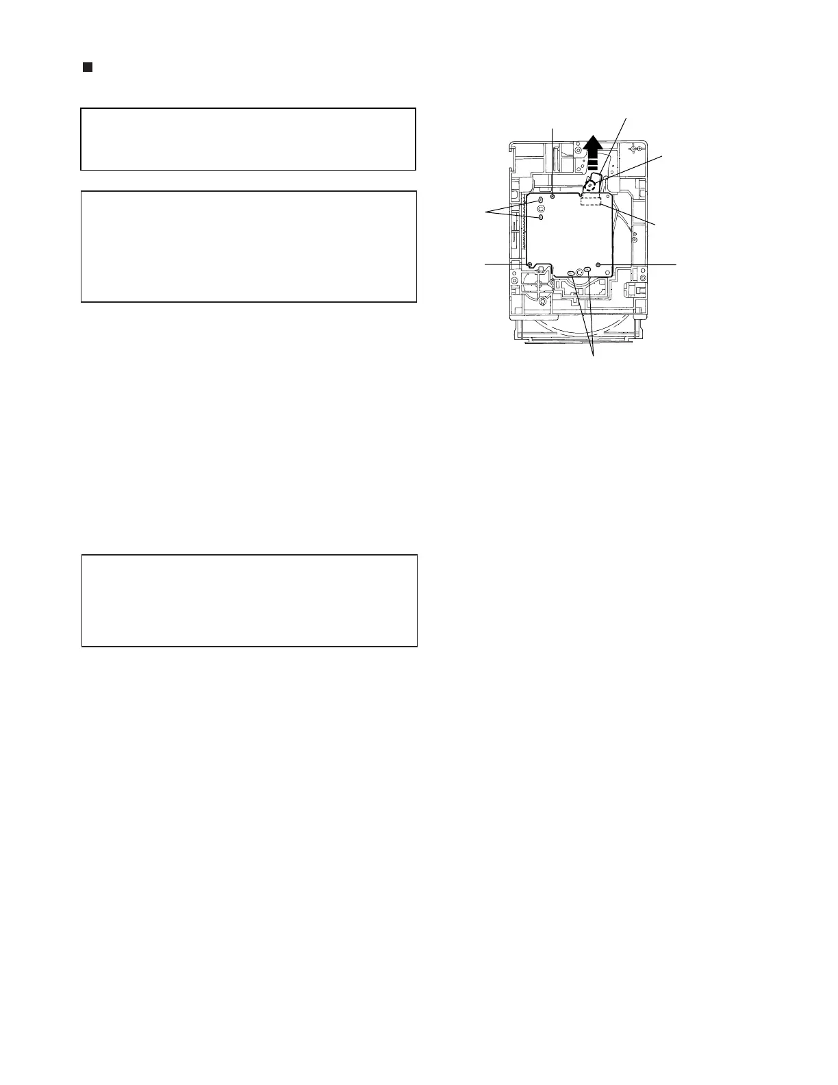
Removing the Mechanism Board
(Refer to Fig 10.)
1. Solder the shorting round of the flexible wire
connected with the mechanism board from the back
of the mechanism assembly.
2. Disconnect the flexible wire from the connector
CN601 on the mechanism board.
3. Remove the three screws C fastening the
mechanism board.
4. Unsolder the two points of the part h and one point
of the part i of the mechanism board. Then, remove
the mechanism board upwards.
Note:When reinstalling the mechanism board,
connect the flexible wire coming from the
pickup to the connector first and then remove
the solder from the shorting round of the
flexible cable.
Fig. 10
C
C
C
CN601 on
mechanism
board
Flexible wire
Shorting round
Soldered
part h
Soldered part i
 Loading...


