1-11
UX-A70MD
Removing the CD mechanism assembly
and the CD servo board
(See Fig.19 to 24)
Prior to performing the following procedure, remove
the rear cover, the side panels, the top cover, the
MD mechanism assembly, the tuner & function
board, the AC jack board, the antenna terminal
board, the front panel assembly and the main board.
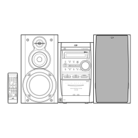
Cut off the two tie band on the back of the CD
mechanism assembly top cover.
Remove the screw M and the top cover.
Move the lever f in the direction of the arrow to draw
the loading tray manually.
Remove the screw N on the CD tray and pull out the
CD tray from the CD mechanism assembly.
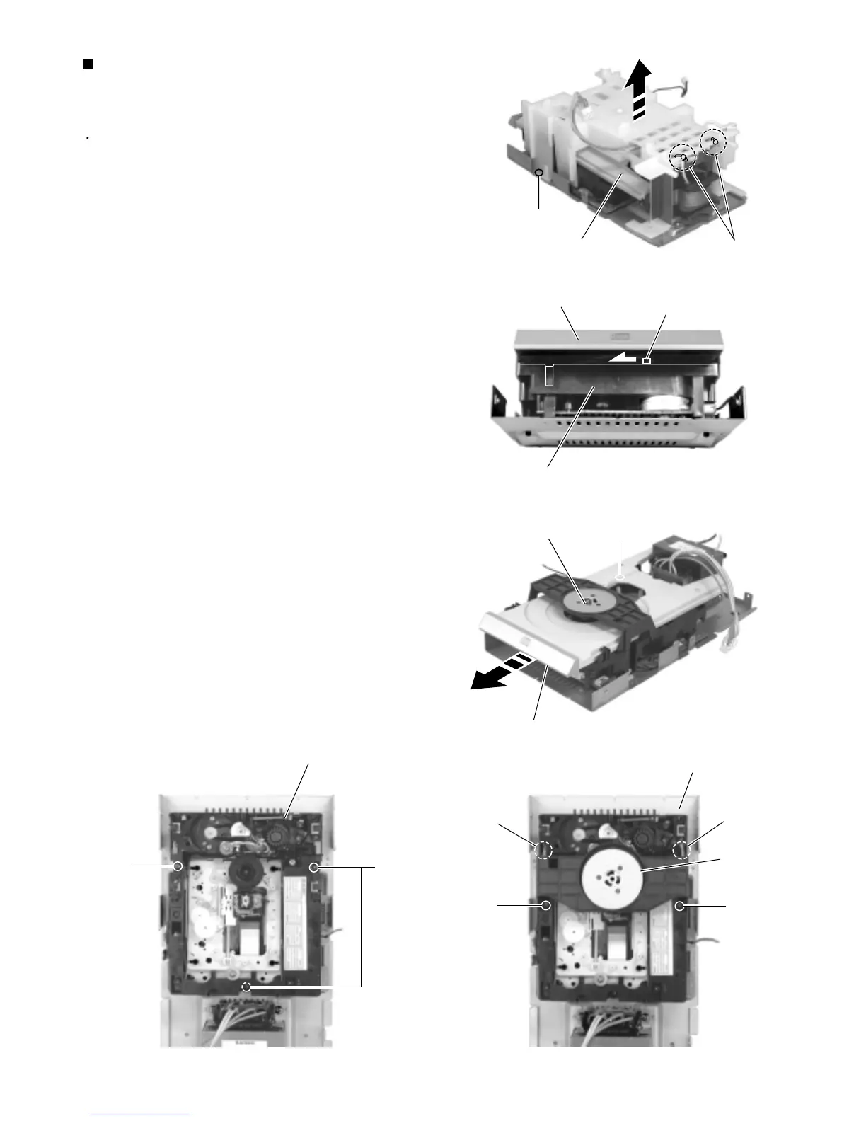
Remove the two screws O attaching the clamper
base on top of the CD mechanism assembly.
Release the two joints g with the CD mechanism
assembly and remove the clamper base upward.
Remove the three screws P attaching the CD
mechanism assembly.
Remove the three screws Q attaching the CD servo
board on the back of the CD mechanism assembly.
Disconnect the harness from connector P031 on the
CD mechanism assembly. Disconnect the harness
and the card wire from connector CN602 and CN601
on the CD servo control board respectively.
1.
2.
3.
4.
5.
6.
7.
8.
M
Tie band
CD mechanism assembly
Fig.19
Lever f
CD mechanism assembly
Fig.21
N
Clamper base
Loading tray
Fig.20
Fig.22
Joint g
Joint g
O
O
CD mechanism assembly
Loading tray
Clamper base
Fig.23
CD mechanism assembly
P
P
 Loading...