1-12
UX-A70MD
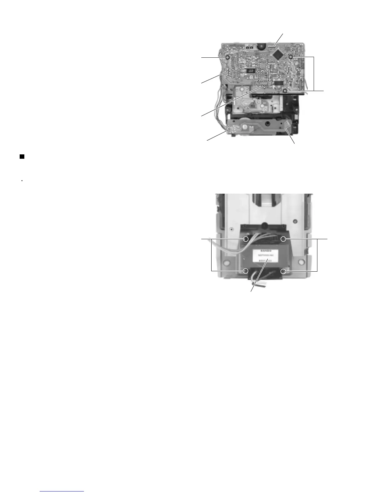
Removing the transformer assembly
(See Fig.19 and 25)
Prior to performing the following procedure, remove
the rear cover, the side panels, the top cover, the
MD mechanism assembly, the tuner & function
board, the AC jack board, the antenna terminal
board, the front panel assembly and the main board.
Cut off the two wire clamp on the back of the CD
mechanism assembly upper cover.
Remove the screw M and the CD mechanism
assembly upper cover.
Remove the four screws R attaching the transformer
assembly.
1.
2.
3.
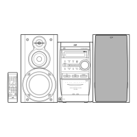
R
P031
CN602
CN601
Q
Q
CD servo board
CD mechanism board
Fig.24
R
Transformer assembly
Fig.25
 Loading...