1-13
UX-A70MD
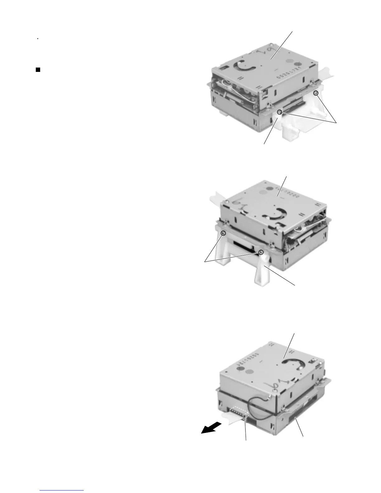
Remove the four screws S attaching the bracket (a)
and (b) on both sides of the MD mechanism
assembly unit.
Disconnect the card wire from connector CN521 on
the MD mechanism board. Remove the MD
mechanism assembly bottom cover downward.
1.
2.
Removing the MD mechanism assembly
(See Fig.26 to 28)
<MD mechanism assembly unit>
Prior to performing the following procedure, remove
the rear cover, the side panels, the top cover unit
and the MD mechanism assembly unit.
S
MD mechanism assembly
Bracket (a)
Fig.26
S
MD mechanism assembly
bottom cover
CN521
Fig.27
Fig.28
MD mechanism assembly
Bracket (b)
MD mechanism assembly
 Loading...