1-14
UX-A70MD
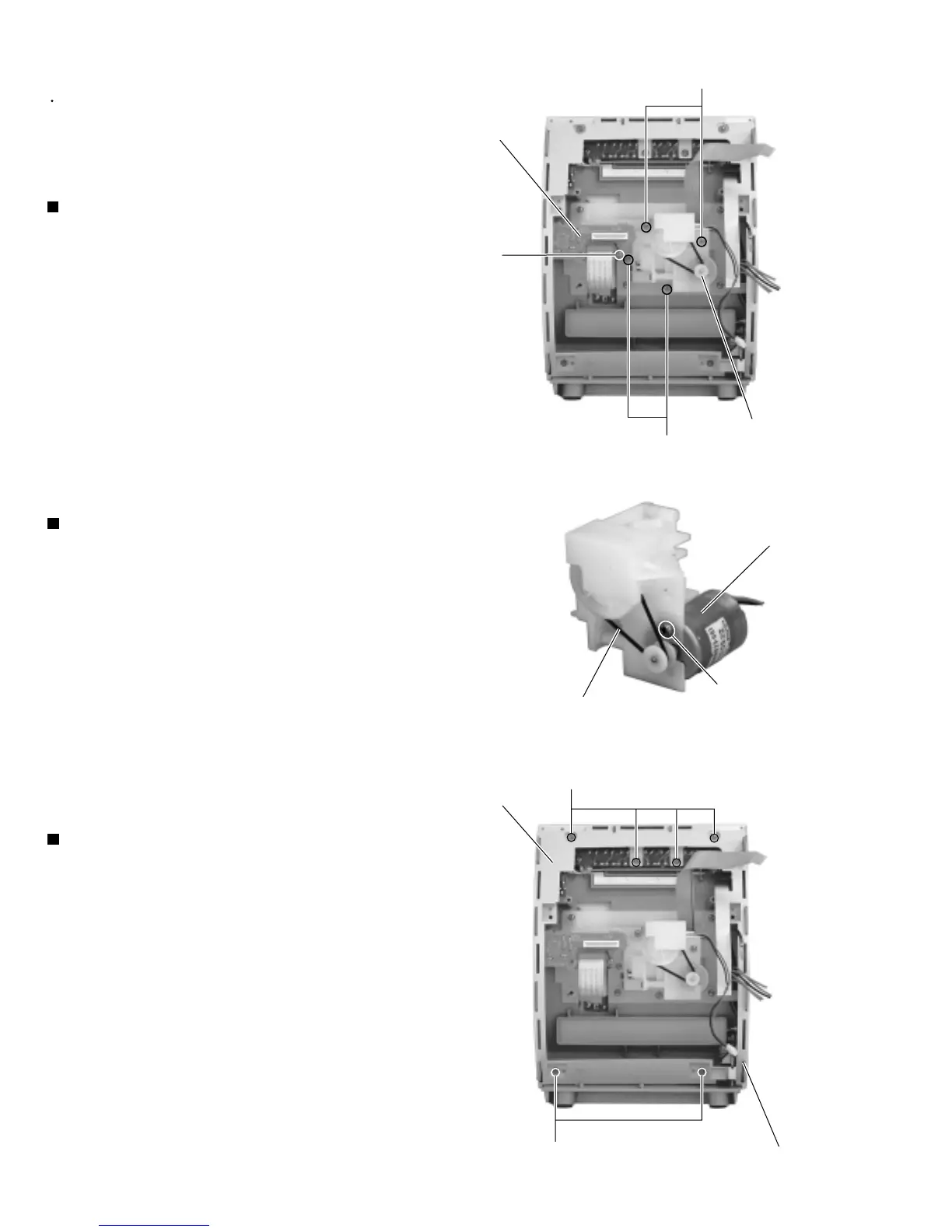
Disconnect the card wire from connector CN908 on
the relay board respectively.
Remove the screw T attaching the relay board.
1.
2.
Removing the relay board (See Fig.29)
<Front panel assembly unit>
Prior to performing the following procedure,remove
the rear cover,the side panels, the top cover, the MD
mechanism assembly unit,the tuner & function board
and the front panel assembly unit.
Remove the four screws U attaching the drive motor
assembly.
Remove the belt and the screw V attaching the
drive
motor.
1.
2.
Removing the drive motor assembly
(See Fig.29 and 30)
Remove the six screws W attaching the bracket (c),
and detach the headphone jack board.
1.
Removing the headphone jack board
(See Fig.31)
Fig.29
Fig.30
Relay board
Drive motor assembly
U
U
Drive motor
Belt
V
W
W
Headphone jack board
Bracket (c)
Fig.31
T
 Loading...