1-26
UX-A70MD
Reattach the wire holder to the UD base while
engaging the UD base hook marked u to the wire
holder slot marked t (At the same time, the boss on
the reverse side of the wire holder is fitted to the UD
base round hole).
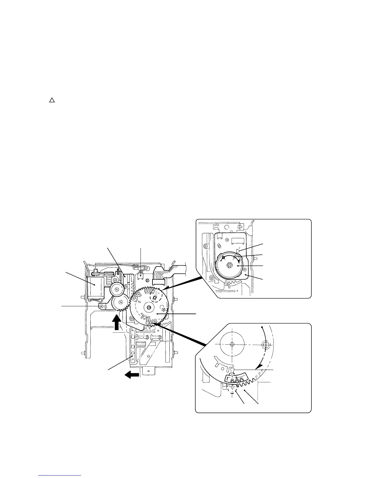
Reattach the cam switch board using the two screws
H. (Fig.22)
Turn the cam switch to bring the boss to the point
marked on the cam switch board. Reattach the
cam gear using a slit washer while fitting the cam
gear slot to the cam switch boss. (Fig.22)
4.
5.
6.
Reattach the loading motor assembly, using the
screw F. Connect the harness extending from the
loading motor to connector CN612 on the switch
board and fix it with the wire holder. (Fig.22)
7.
When reattaching the cam gear, the
cam switch boss should be fitted to the
cam gear slot, and the triangle mark of
the cam gear should be aligned to the
hole of the eject bar as shown in
Fig.22.
ATTENTION:
Fig.22
F
Cam switch
Boss
Point marked
Cam switch board
Cam gear
Slide bar CN612
Loading motor assembly
Eject lever
Eject lever
Cam gear
(Triangle mark)
n
 Loading...