UX-A7DVD
(No.22013)1-11
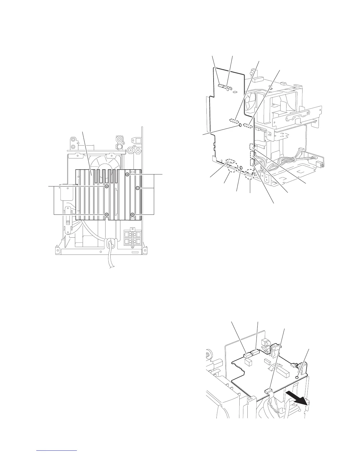
2.1.8 Removing the main board
(See Fig.20, 21)
• Prior to performing the following procedure, remove the metal
cover, the DVD mechanism assembly, the front panel assem-
bly and the rear cover/ rear panel.
(1) Remove the two screws M and the three screws N, and
then remove the heat sink.
(2) Disconnect the wires from connector CN307 and CN310,
the card wire from CN312 on the main board on the left side
of the body.
(3) Remove the screw O and P attaching the main board.
(4) Disconnect connector CN303, CN304, CN305 and CN306
on the main board. Release the two joints e at the bottom.
(5) Draw out the main board and disconnect the wire from con-
nector CN311.
Fig.20
Fig.21
2.1.9 Removing the DVD relay board
(See Fig.22)
• Prior to performing the following procedure, remove the metal
cover, the DVD mechanism assembly and the rear cover/ rear
panel.
(1) Disconnect the card wire from connector CN515 on the
DVD relay board.
(2) Remove the screw Q attaching the DVD relay board on top
of the body.
(3) Disconnect connector CN511 and CN512 on the DVD relay
board.
Fig.22
M
N
Heat sink
Main board
CN303
CN304
CN305
CN306
CN312
CN307
CN310
P
e
e
CN311
O
Q
DVD relay baoard
CN512 CN511
CN515
 Loading...