EasyManuals Logo

JVC UX-A7DVD User Manual

JVC UX-A7DVD
66 pages
To Next Page IconTo Next Page
To Previous Page IconTo Previous Page
Page #20 background imageLoading...
Page #20 background image
UX-A7DVD
1-20 (No.22013)
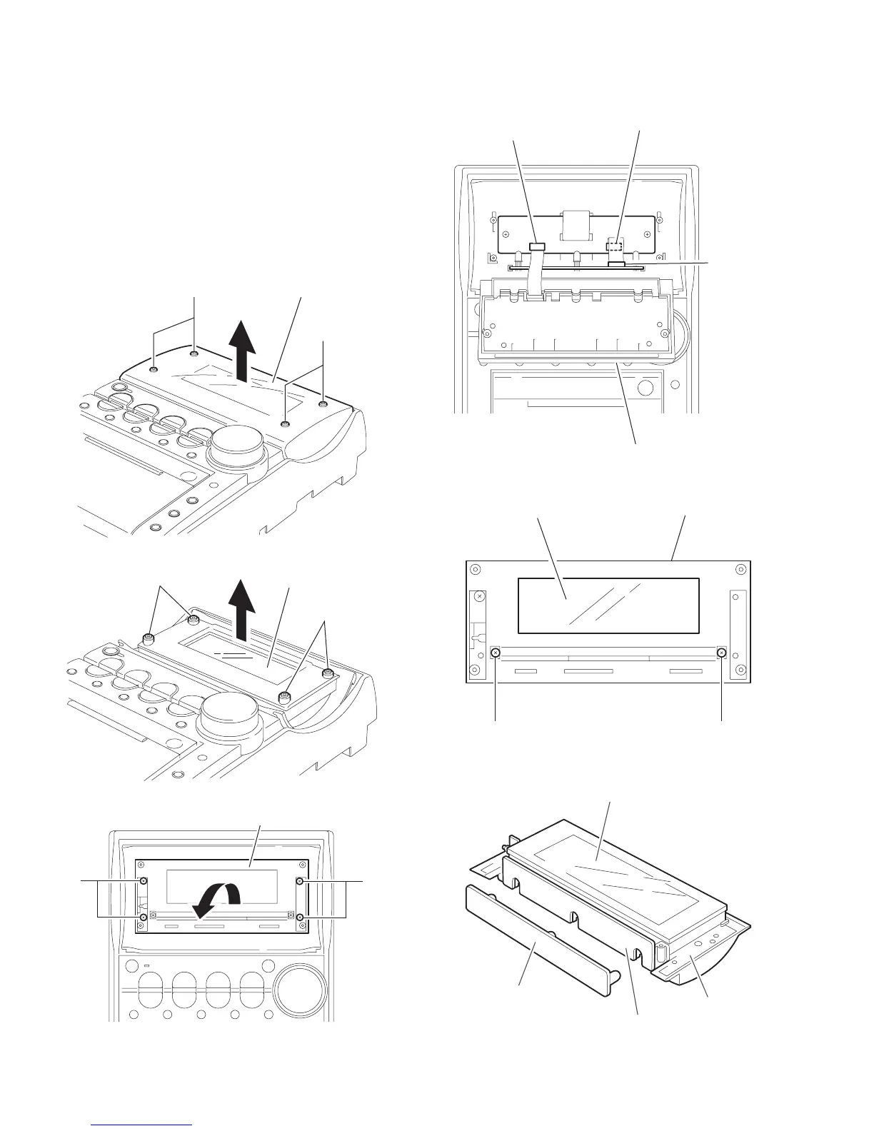
2.2.8 Removing the FL display section
(See Fig.43~48)
(1) Remove the four screws AE attaching the case cover on
the front panel.
(2) Pull out the FL panel from the four joint bosses m on the FL
display cover.
(3) Remove the four screws AF attaching the FL display cov-
er. Disconnect the card wire from connector CN451 and
CN452 on the FL relay board.
(4) Remove the two screws AG attaching the FL display on
the FL display cover.
(5) The FL board and the lens come off from the FL display
section.
Fig.43
Fig.44
Fig.45
Fig.46
Fig.47
Fig.48
AE
AE
Case cover
m
m
FL panel
A
FAF
FL display cover
FL relay board
CN451
CN452
FL display cover
LED board
CN461
AG AG
FL display section
FL display cover
FL board
FL display section
LED board
Lens

Questions and Answers:

Question and Answer IconNeed help?

Do you have a question about the JVC UX-A7DVD and is the answer not in the manual?

JVC UX-A7DVD Specifications

General IconGeneral
BrandJVC
ModelUX-A7DVD
CategoryStereo System
LanguageEnglish

Related product manuals