2-4
UX-G6/FS-G6
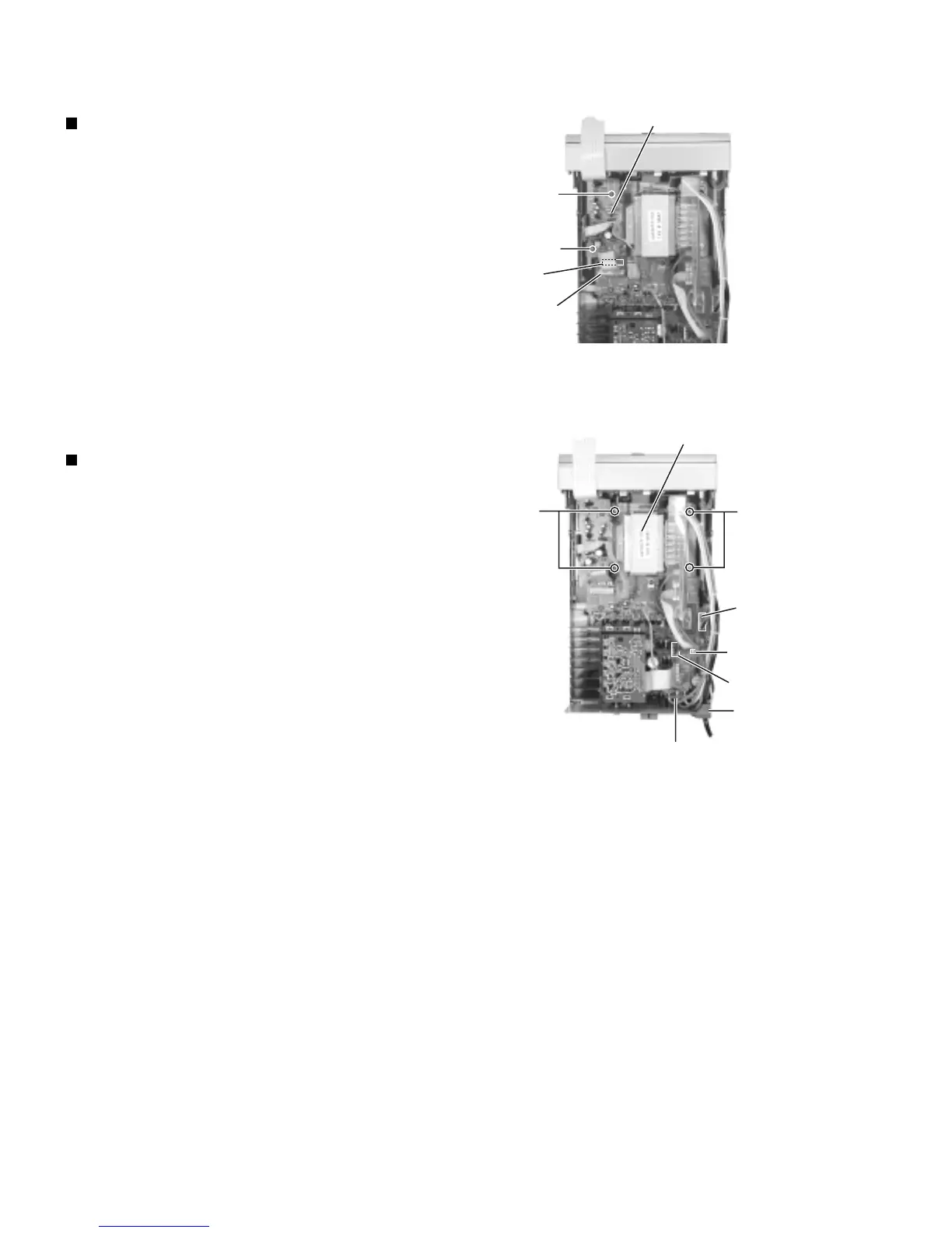
Removing the regulator board
(See Fig.10)
• Prior to performing the following procedure,
remove the top cover.
1. Disconnect the card wire from connector CN908
on the main board.
2. Disconnect the harness from connector CN906
on the main board.
3. Remove the two screws G attaching the regula-
tor board.
Removing the transformer assembly
(See Fig.11)
• Prior to performing the following procedure,
remove the top cover.
1. Disconnect the harness from connector CN904,
CN905 and CN903 on the main board.
2. Remove the four screws H attaching the trans-
former assembly.
3. Remove the cord stopper and the voltage selec-
tor as shown in Fig.9.
(If necessary, unsolder the soldered point and cut
off the belt fixing the harness.)
Fig. 10
Fig. 11
G
G
Regulator board
Main board
CN908
CN906
HH
CN905
CN903
CN904
Cord stopper
Voltage selector
Power transformer

 Loading...