2-5
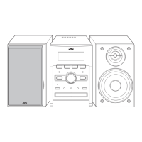
UX-G6/FS-G6
Fig. 12
Fig. 13
Fig. 14
Fig. 15
Fig. 16
Fig. 17Fig. 18
I
I
J
CN907
CN906
CN908
CN905
CN903
CN904
Main board
Heat sink
K
L
J
Main board
Slide bracket
Part f
Micro-switch
L
CN910
Heat sink
Main board
Amplifier board
M
N
Heat sink
Main board
L
Heat sink
Amplifier board
Main board
CN911
Part e
Sub board
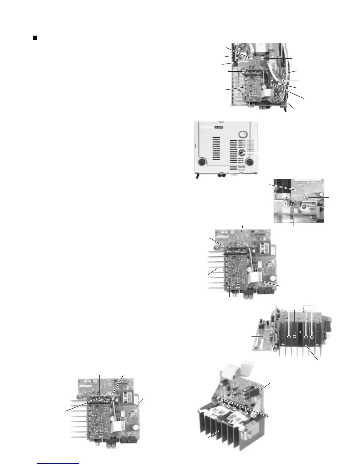
Removing the main board and the heat sink
(See Fig.11 to 18)
• Prior to performing the following procedure, remove
the top cover and the rear cover.
1. Disconnect the harness or card wire from connector
CN903, CN904, CN905, CN906, CN907 and CN908
on the main board.
2. Remove the two screws I attaching the main board
and the screw J attaching the heat sink.
3. Remove the screw K attaching the heat sink on the
bottom of the body.
The main board will come off along with the heat
sink.
ATTENTION: When reattaching, make sure that the
part "f" micro-switch on the main board
is correctly attached to the elbowed
slide bracket.
(When removing the heat sink.)
4. Disconnect the harness from connector CN910 on
the main board.
5. Remove the screw L and the four screws M attach-
ing the heat sink on the main board.
6. Remove the seven screws N attaching the amplifier
board.
(When removing the sub board from the main board.)
7. Disconnect the harness fixed to the part "e" on the
main board.
Disconnect the sub board from connector CN911 on
the main board.

 Loading...