2-12
UX-G6/FS-G6
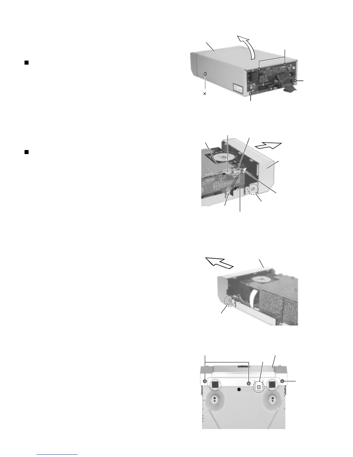
Fig. 1
Fig. 2
Fig. 3
Fig. 4
A 2
Top cover
B
B
B
System control board
CN501
CN451
Analog in/digital out board
C
Joint b
Front panel assembly
Tie band
Front panel assembly
Joint b
Joint a
D
D
Front panel assembly
Disassembly method
(XT-UXG6)
Removing the top cover (See Fig.1)
1. Remove the two screws A and the four screws B
attaching the top cover. Remove the top cover in
the direction of the arrow while pulling it.
Removing the front panel assembly
(See Fig.2 to 4)
• Prior to performing the following procedure,
remove the top cover.
1. Cut the tie band fixing the harness on the side of
the body. Remove the screw C and the harness
on the side of the analog in/digital out board.
Disconnect the harness from connector CN451.
2. Disconnect the harness from connector CN501
on the system control board.
3. Remove the three screws D on the bottom of the
body.
4. Release the joint "a" on the bottom and the joints
"b" on both sides of the body respectively.

 Loading...