2-13
UX-G6/FS-G6
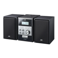
Removing the front panel assembly
(See Fig.5 and 6)
• Prior to performing the following procedure,
remove the top cover.
1. Remove the seven screws E attaching the rear
panel on the back of the body and release the
two joints "c" on both sides while moving the rear
panel upward.
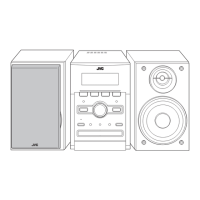
2. Disconnect the harness from connector CN431
on the main & CD servo board.
(When disconnecting the harness from the rear
panel, unhook the upper and lower four hooks of
the wire stopper on the back of the rear panel
and pull out the harness outward.)
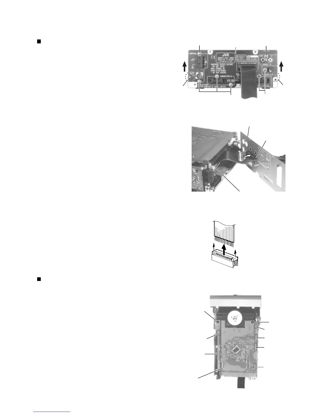
Removing the system control board
(See Fig.7)
• Prior to performing the following procedure,
remove the top cover and the rear panel.
1. Disconnect the harness from connector CN501
and CN506 on the system control board respec-
tively.
2. Remove the two screws F attaching the system
control board.
3. Disconnect connector CN502, CN503, CN504
and CN507 on the system control board while
pulling out them.
Fig. 5
Fig. 6
Fig. 7
Fig.6-1
CAUTION: Lift the lock and
pull out the wire.
Rear panel
EE
E
E
joint c
joint c
CN431
Rear panel
Main & CD servo board
CN431
Wire stopper
F
F
CN506
CN507
CN504
CN503
CN502
CN501
System control
board

 Loading...