2-15
UX-G6/FS-G6
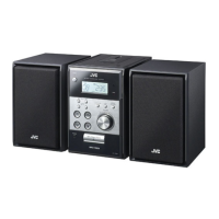
Removing the CD mechanism assembly
main & CD servo board (See Fig.12 to 14)
• Prior to performing the following procedure,
remove the top cover, the front panel assembly,
the rear panel, the system control board and the
analog in/digital out board.
1. Remove the three screws I attaching the CD
mechanism assembly and the screw J attaching
the main & CD servo board.(The CD mechanism
assembly will be detached together with the main
& CD servo board.)
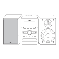
2. Remove the three screws K attaching the main &
CD servo board.
3. Disconnect the harness from connector CN440
and CN438 on the main & CD servo board on the
back of the CD mechanism assembly.
4. Remove the card wire from connector CN439 on
the main & CD servo board.
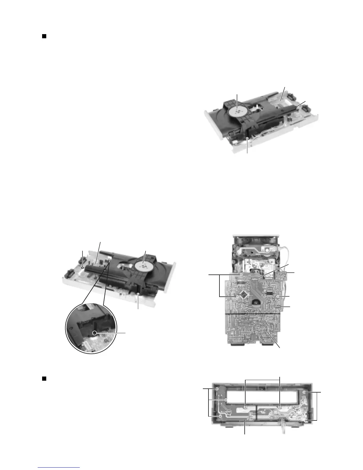
Removing the front board (See Fig.15)
• Prior to performing the following procedure,
remove the top cover and the front panel assem-
bly.
1. Remove the seven screws L attaching the front
board in the front panel assembly.
Fig. 12
Fig. 13
Fig. 14
Fig. 15
J
I
CD mechanism assembly
Main & CD servo board
I
J
Main & CD servo board
CD mechanism assembly
CN440
CN438
CN439
K
K
Main & CD servo board
L
L
L
Front board
I

 Loading...