1-12 (No.MB665<Rev.004>)
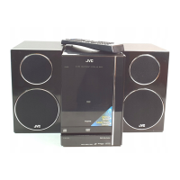
3.1.8 Removing the Micom board (See Fig.15, 16)
(1) Remove the two screws J attaching the Micom board. (See
Fig.15)
(2) Disconnect the flat cable wire from Micom board connected
to connector CN201
and CN203 of the Power board. (See
Fig.16)
(3) Disconnect the board to board connector connected to
connector CN204
of the Power board. (See Fig.16)
(4) Disconnect the board to board connector connected to
connector CN803 of the USB jack board. (See Fig.16)
Fig.15
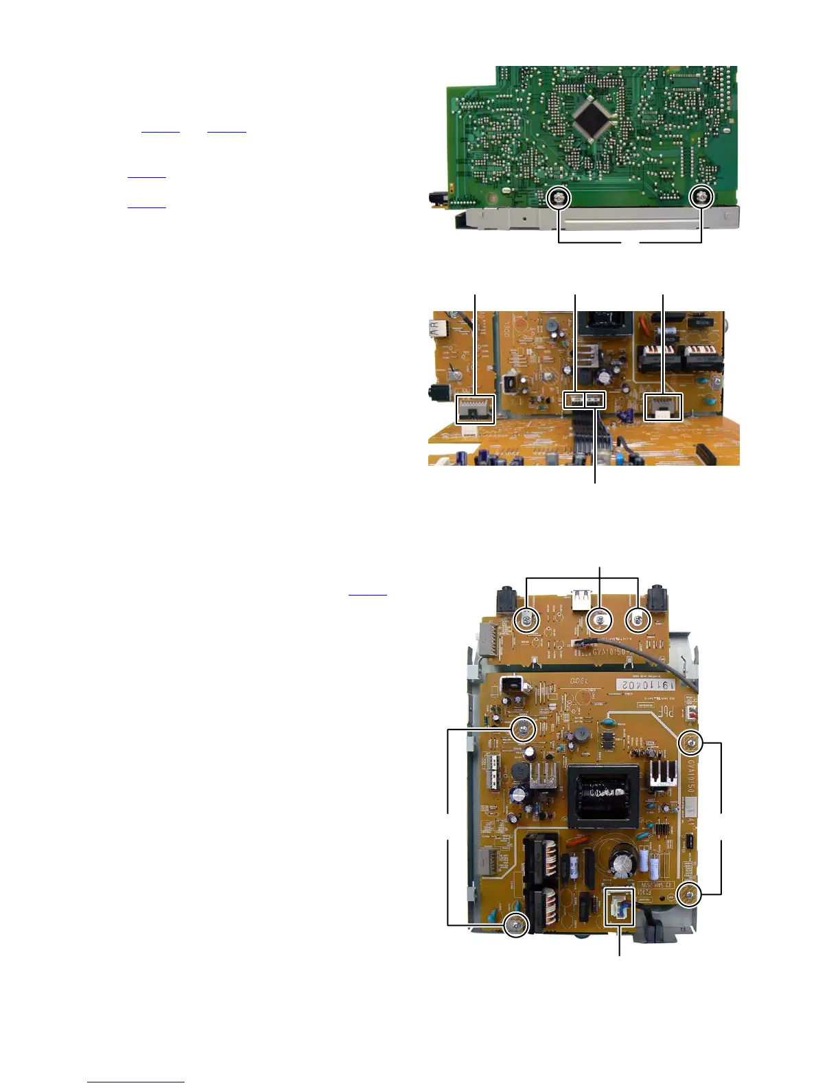
Fig.16
3.1.9 Removing the USB jack board (See Fig.17)
(1) Remove the three screws K attaching the USB jack board.
3.1.10 Removing the Power board (See Fig.17)
(1) Disconnect the power cord connected to connector CN200
of the Power board.
(2) Remove the four screws L attaching the Power board.
Fig.17
J
CN204CN803 CN203
CN201
CN200
K
LL
 Loading...