1-12 (No.MB024)
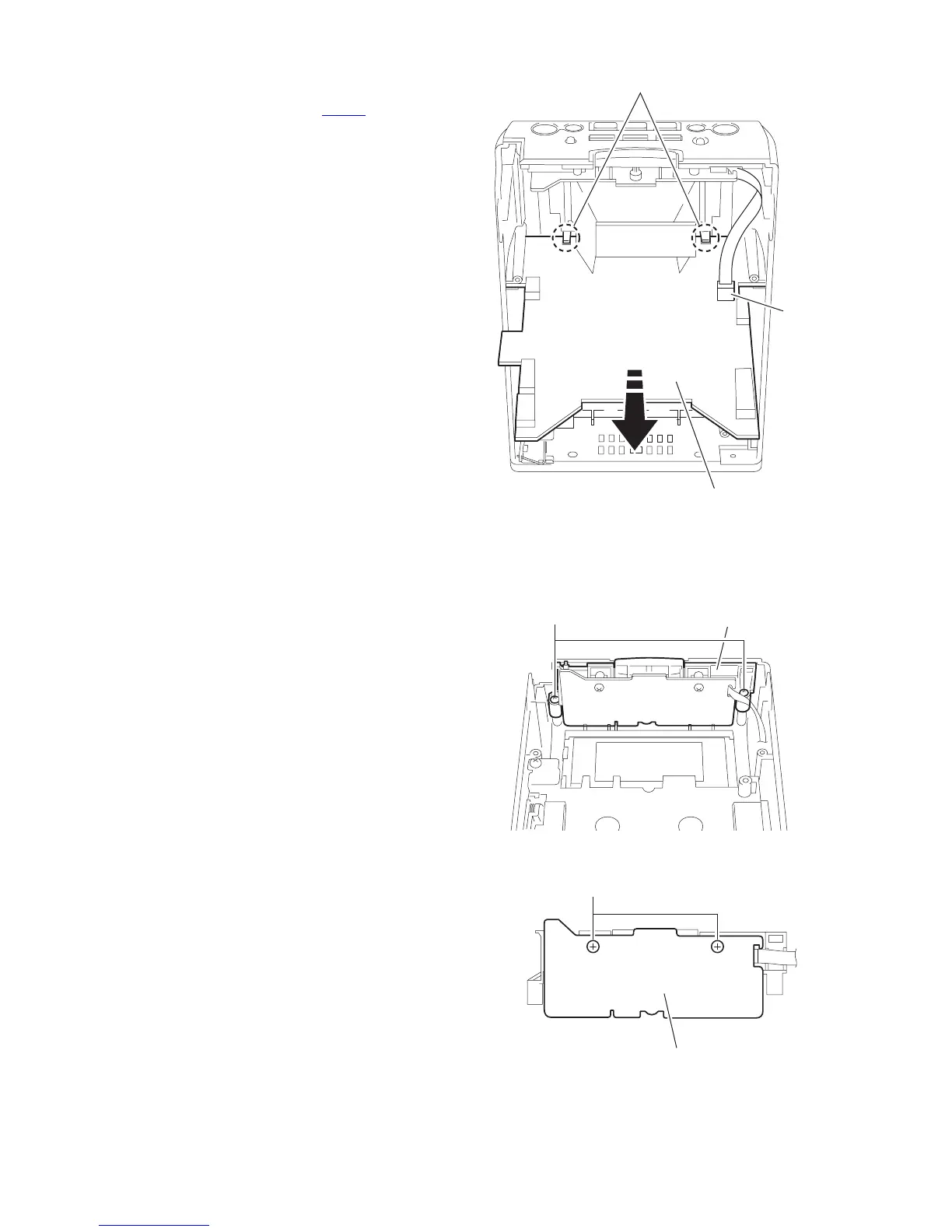
3.1.9 Remove the LCD system CPU board
(See Fig.18)
(1) Disconnect the wire from the connector CN716
on the LCD
system CPU board.
(2) Release the two joints f and pull out the LCD system CPU
board.
Fig.18
3.1.10 Removing the operating switch board
(See Fig.19,20)
• Prior to performing the following procedure, remove the front
panel assembly, the cassette mechanism assembly and the
LCD system CPU board.
(1) Remove the two screws M attaching the operating switch
button.
(2) Remove the two screws N attaching the operating switch
board, and remove.
Fig.19
Fig.20
f
LCD system CPU board
CN716
M Operating switch button
N
Operating switch board
 Loading...