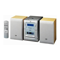
EasyManua.ls Logo

JVC UX-HB4

JVC UX-HB4
51 pages
To Next Page IconTo Next Page
Loading...
SERVICE MANUAL
COPYRIGHT © 2004 Victor Company of Japan, Limited
No.MB330
2004/10
MICRO COMPONENT SYSTEM
MB330200410
UX-HB4
TABLE OF CONTENTS
1 PRECAUTION. . . . . . . . . . . . . . . . . . . . . . . . . . . . . . . . . . . . . . . . . . . . . . . . . . . . . . . . . . . . . . . . . . . . . . . . . 1-3
2 SPECIFIC SERVICE INSTRUCTIONS . . . . . . . . . . . . . . . . . . . . . . . . . . . . . . . . . . . . . . . . . . . . . . . . . . . . . . 1-7
3 DISASSEMBLY . . . . . . . . . . . . . . . . . . . . . . . . . . . . . . . . . . . . . . . . . . . . . . . . . . . . . . . . . . . . . . . . . . . . . . . 1-8
4 ADJUSTMENT . . . . . . . . . . . . . . . . . . . . . . . . . . . . . . . . . . . . . . . . . . . . . . . . . . . . . . . . . . . . . . . . . . . . . . . 1-20
5 TROUBLESHOOTING . . . . . . . . . . . . . . . . . . . . . . . . . . . . . . . . . . . . . . . . . . . . . . . . . . . . . . . . . . . . . . . . . 1-23
CA-UXHB4 SP-UXHB4SP-UXHB4
Area suffix
B ------------------------------ U.K.

Questions and Answers:

JVC UX-HB4 Specifications

General IconGeneral
BrandJVC
ModelUX-HB4
CategoryStereo System
LanguageEnglish

Summary

Safety Precautions and Warnings

General Safety Guidelines

Covers essential safety practices for servicing, including electrical hazards and component handling.

Static Electricity Prevention for Repairs

Techniques to prevent ESD damage to sensitive components like laser diodes during servicing.

Laser Product Safety Information

Important safety notes concerning Class 1 laser products and potential radiation exposure.

Disassembly Procedures

Front Panel Assembly Removal

Step-by-step guide for detaching the front panel assembly from the main unit.

Main Board Removal Steps

Instructions for disconnecting wires and safely removing the main board.

CD Mechanism and Board Disassembly

Procedures for removing the CD mechanism assembly and its related board.

Cassette Mechanism Assembly Removal

Guide to opening the cassette door and detaching the cassette mechanism.

Heat Sink and Power Board Removal

Steps for removing the heat sink and power board components from the unit.

Adjustment Procedures

Cassette Amplifier Section Adjustments

Details on performing head azimuth and tape speed adjustments for the cassette section.

Tuner Section Alignment

Procedures for AM/FM IF and tracking adjustments within the tuner section.

Location of Adjustment Points

Diagrams illustrating the physical placement of adjustable components on internal boards.

Schematic Diagrams and Circuit Layouts

System Wiring Connection Diagram

Illustrates the electrical wiring paths between various system components.

Functional Block Diagram

Provides a high-level overview of the system's functional blocks and their interconnections.

Power Circuit Schematic Diagram

Detailed schematic for the power supply circuit, including critical component identification.

Main Circuit Schematic Details

Schematic detailing the primary functional circuits of the audio system.

Parts List and Identification

Exploded View of General Assembly

Visual exploded view of the unit's components with associated part numbers.

Electrical Component Parts List

Comprehensive list of electrical components with specifications and part numbers.

Packing and Accessory Parts

Details of packaging materials and accessories included with the product.

Related product manuals