UX-M5R
1-10
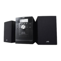
Fig.17
Stud
Radio pliers, etc.
Power board
Chassis
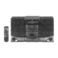
Fig.18
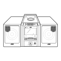
Fig.16
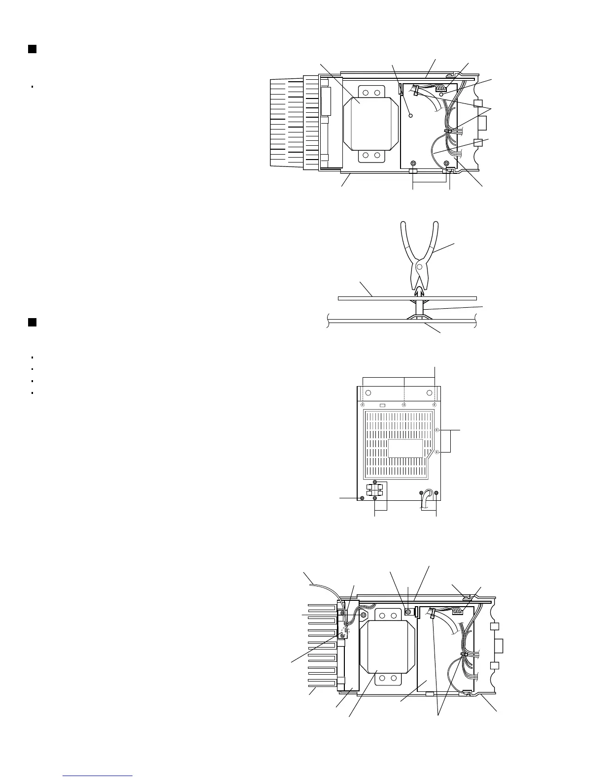
Fig.19
NM
Chassis
Tie bands
Lug wire
CN901
Power board
Main board
Stud
StudPower transformer
P
R
P
QR
S
T
Chassis
Tie bands
CN901
Power board
Main board
Soldered
part e
FM antenna wire
Regulator IC
(IC302)
Power transformer
Heat sink
Antenna board
Stud
Bracket
Removing the power board
(See Figs. 16 and 17.)
1.
2.
3.
4.
5.
Remove the left and right side panels.
Disconnect the wires from the connector CN901 on
the power board.
Remove the tie bands bundling the wires.
Remove the screw M retaining the lug wire.
Remove the two screws N retaining the chassis .
Remove the power board by pinching the two studs
retaining the power board using radio pliers, etc.
Removing the main board
(See Figs. 18 and 19.)
1.
2.
3.
4.
5.
6.
7.
8.
9.
Remove the left and right side panels.
Remove the top cover.
Remove the front panel assembly.
Remove the CD mechanism assembly.
From the inside of the rear panel, remove the five
screws P retaining the bracket.
Remove the two screws Q retaining the speaker
terminal of the main board.
Remove the solder from the soldered part e that
attaches the FM antenna wire to the antenna
board.
Remove the three screws R retaining the rear
panel, then remove the rear panel.
From the top side of the main body, remove the
screw S retaining the bracket of the main board.
Remove the screw T retaining the regulator
IC(IC302).
Remove the tie bands bundling the wires.
Disconnect the wire from the connector CN901 on
the power board.
Remove the stud on the main board, and then take
out the main board from the chassis.
 Loading...