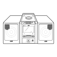
UX-M5R
1-33
GND
L-IN1
L-IN2
L-IN3
L-IN4
L-SW-OUT
L-VR-IN
L-B1
L-B2
L-B3
L-TONE-OUT
L-T1
Vref
CK
DATA
STB
R-T1
R-TONE-OUT
R-B3
R-B2
R-B1
R-VR-IN
R-SW-OUT
R-IN4
R-IN3
R-IN2
R-IN1
VDD
1
2
3
4
5
6
7
8
9
10
11
12
13
14
15
16
17
18
19
20
21
22
23
24
25
26
27
28
Ground pin
Audio signal input pin (L-ch)
Audio signal input pin (L-ch)
Audio signal input pin (L-ch)
Audio signal input pin (L-ch)
Audio signal output pin (L-ch)
Main volume input pin (L-ch)
Tone control tap pin 1 for bus
Tone control tap pin 2 for bus
Tone control tap pin 3 for bus
Tone control output pin (L-ch)
Tone control tap pin for treble (L-ch)
Reference voltage input pin
Clock input pin
Data input pin
Strobe input pin
Tone control tap pin for treble (R-ch)
Tone control output pin (R-ch)
Tone control tap pin 3 for bus
Tone control tap pin 2 for bus
Tone control tap pin 1 for bus
Main volume input pin (R-ch)
Audio signal output pin (R-ch)
Audio signal input pin (R-ch)
Audio signal input pin (R-ch)
Audio signal input pin (R-ch)
Audio signal input pin (R-ch)
Power supply voltage pin
-
I
I
I
I
O
I
I
I
I
O
I
I
I
I
I
I
O
I
I
I
I
O
I
I
I
I
-
3.Pin Function
Pin No. Symbol I/O Function
 Loading...