1-12 (No.MB230)
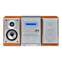
3.1.8 Removing the main board (See Fig.17)
• Prior to performing the following procedures, remove the side
panels L/R, top cover assembly and rear cover.
Reference:
Remove the tuner as required. (See 3.1.6 "Removing the tuner")
(1) From the right side of the main body, remove the two
screws N attaching the main board.
(2) Remove the main board to the direction of this side and dis-
connect the connectors CN761
and CN762 on the main
board.
(3) From the forward side of the main board, disconnect the
card wires from the connectors CN700
, CN763 and CN764
on the main board.
(4) Disconnect the wire from the connector CN767
on the for-
ward side of the main board.
Fig.17
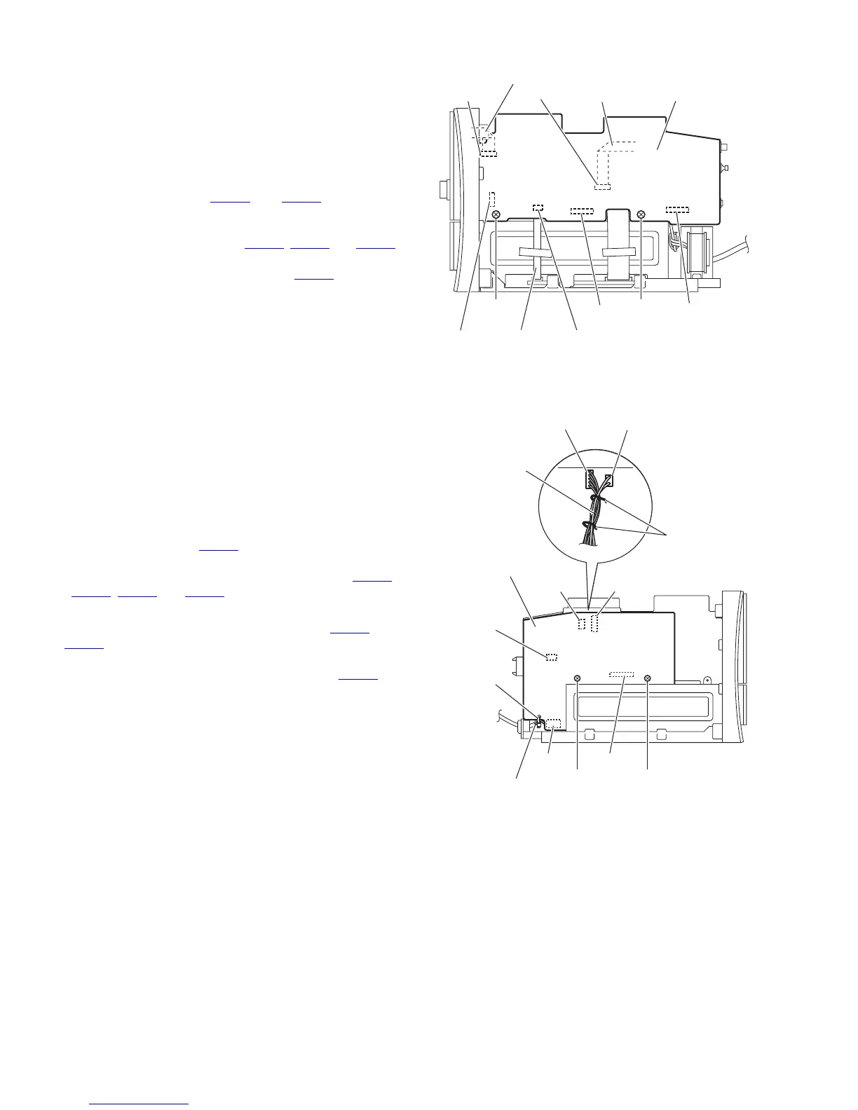
3.1.9 Removing the power supply board (See Fig.18)
• Prior to performing the following procedures, remove the side
panels L/R, top cover assembly and rear cover.
Reference:
Remove the tuner as required. (See 3.1.6 "Removing the tuner")
(1) From the left side of the main body, remove the two screws
P attaching the power supply board.
(2) Cut off the tie band bundling the power cord.
(3) Remove the power supply board toward this side and dis-
connect the connector CN902
on the power supply board.
(4) From the forward side of the power supply board, discon-
nect the power cord and wires from the connectors CN901
,
CN904, CN905 and CN907 on the power supply board.
Reference:
• When connecting the wires to the connectors CN904
and
CN905
on the power supply board, bundling the wires with
the wire clamps as before.
• After connecting the power cord to the connector CN901 on
the power supply board, bundle the power cord with the new
tie band as before.
Fig.18
Card wire
Main board
Card wire
CN761
N N
CN764
CN762
CN763Card wire
CN767
CN700
Power supply board
Tie band
Power cord
P P
CN902
CN907
CN904
CN905
CN905
CN904
Wire clamps
Wires
CN902
 Loading...