(No.MB230)1-17
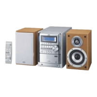
3.1.16 Removing the FL board (See Fig.29)
• Prior to performing the following procedures, remove the side
panels L/R, top cover and front panel assembly.
(1) From the inside of the front panel assembly, remove the
five screws AA attaching the FL board.
(2) Take out the FL board from the front panel assembly and
remove the solders from the soldered section p to remove
the parallel wire.
Reference:
When attaching the FL board, align the projection q of the front
panel assembly in the hole of the FL board.
3.1.17 Removing the headphone jack board (See Fig.29)
• Prior to performing the following procedures, remove the side
panels L/R, top cover and front panel assembly.
(1) From the inside of the front panel assembly, remove the
screw AB and screw AB' attaching the headphone jack
board.
(2) Take out the headphone jack board with the wires.
Reference:
• When attaching the wires, attach the washer board with the
screw AB'.
• After attaching the headphone jack board, fix the wires with
the spacer.
Fig.29
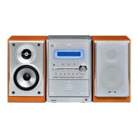
3.1.18 Removing the switch board (See Figs.30 and 31)
• Prior to performing the following procedures, remove the side
panels L/R, top cover, front panel assembly and FL board.
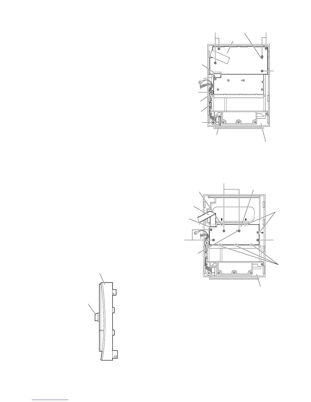
(1) From the front side of the front panel assembly, pull out the
volume knob. (See Fig.30)
(2) From the inside of the front panel assembly, remove the
five screws AC attaching the switch board. (See Fig.31)
(3) Release the claws r in the direction of the arrow and re-
move the switch board from the joints s of the front panel
assembly. (See Fig.31)
(4) Take out the switch board from the front panel assembly.
Reference:
• Remove the parallel wire from the soldered section t on the
switch board as required. (See Fig.31)
• When attaching the switch board, align the projection u of
the front panel assembly in the hole of the switch board.
(See Fig.31)
Fig.30
Fig.31
AA AA
AA
AB'
AB
FL board
Front panel assembly
Projection q
Solder
section p
Parallel wire
Washer board
Spacer
Headphone jack board
Front panel assembly
Volume knob
Front panel assembly
Parallel wire
AC
AC AC
Projection u
Claws r
Joints s
Claw r
Solder
section t
Switch board
 Loading...