1-26 (No.MB230)
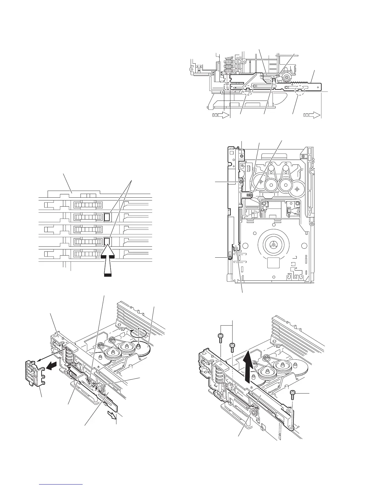
3.2.12 Removing the side (R) assembly
(See Fig.22 to 26)
• Prior to performing the following procedures, remove the tray
assemblies and DVD servo board.
(1) From the inside of the side (R) assembly, release the two
tabs u of the gear cover and remove the gear cover out-
ward. (See Figs.22 and 23.)
(2) From the right side of the DVD changer mechanism as-
sembly, remove the elevator spring attached to the hook v
of the loader assembly. (See Figs.23 and 24.)
(3) From the top side of the DVD changer mechanism assem-
bly, turn the gear 1 clockwise to move the elevator cam
rearward. (See Fig.24.)
(4) Move the two slots w and joint x of the elevator cam and
remove the elevator cam outward. (See Fig.24.)
(5) Remove the three screws V and detaches the side (R) as-
sembly upward. (See Figs.25 and 26.)
Note:
When reattaching the side (R) assembly, make sure to fit the
shaft (part y) into the slot of the select lever. (See Fig.25.)
Fig.22
Fig.23
Fig.24
Fig.25
Fig.26
u
Side(R) assembly
Side(R) assembly
Elevator
Gear cover
Elevator cam
v
Gear 1
Loader assembly
Elevator cam
Elevator spring
v
ww
x
V
Side(R) assembly
V
V
y
Select lever
Side(R) assembly
V
V
 Loading...