1-8 (No.MB230)
3.1.2 Removing the top cover (See Figs.5 to 7)
• Prior to performing the following procedure, remove the side
panels L/R.
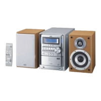
(1) From the back side of the main body, remove the screw E
attaching the top cover to the rear cover. (See Fig.5)
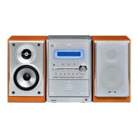
(2) From the right side of the main body, disconnect the card
wires from the connectors CN790
and CN791 on the main
board. (See Fig.6)
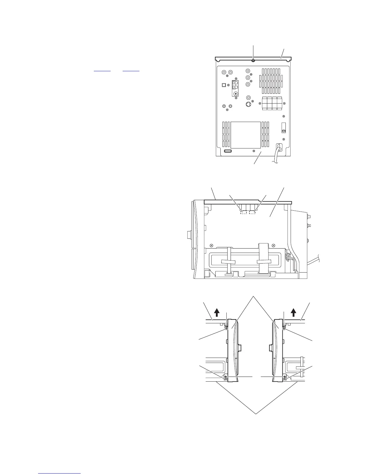
(3) From the both sides of the main body, remove the two
screws F attaching the top cover to the front panel assem-
bly. (See Fig.7)
(4) Release the claws b and remove the top cover from the
main body in the direction of the arrow. (See Fig.7)
Fig.5
Fig.6
Fig.7
Rear cover
Top cove
E
Top Cover
Main board
CN791 CN790
F
F
Claw b
Claw b
G
Claw c
Claw c
Front panel assembly
Bottom chassis
Top coverTop cover
 Loading...