XV-521BK/523GD/525BK/421BK
1-10
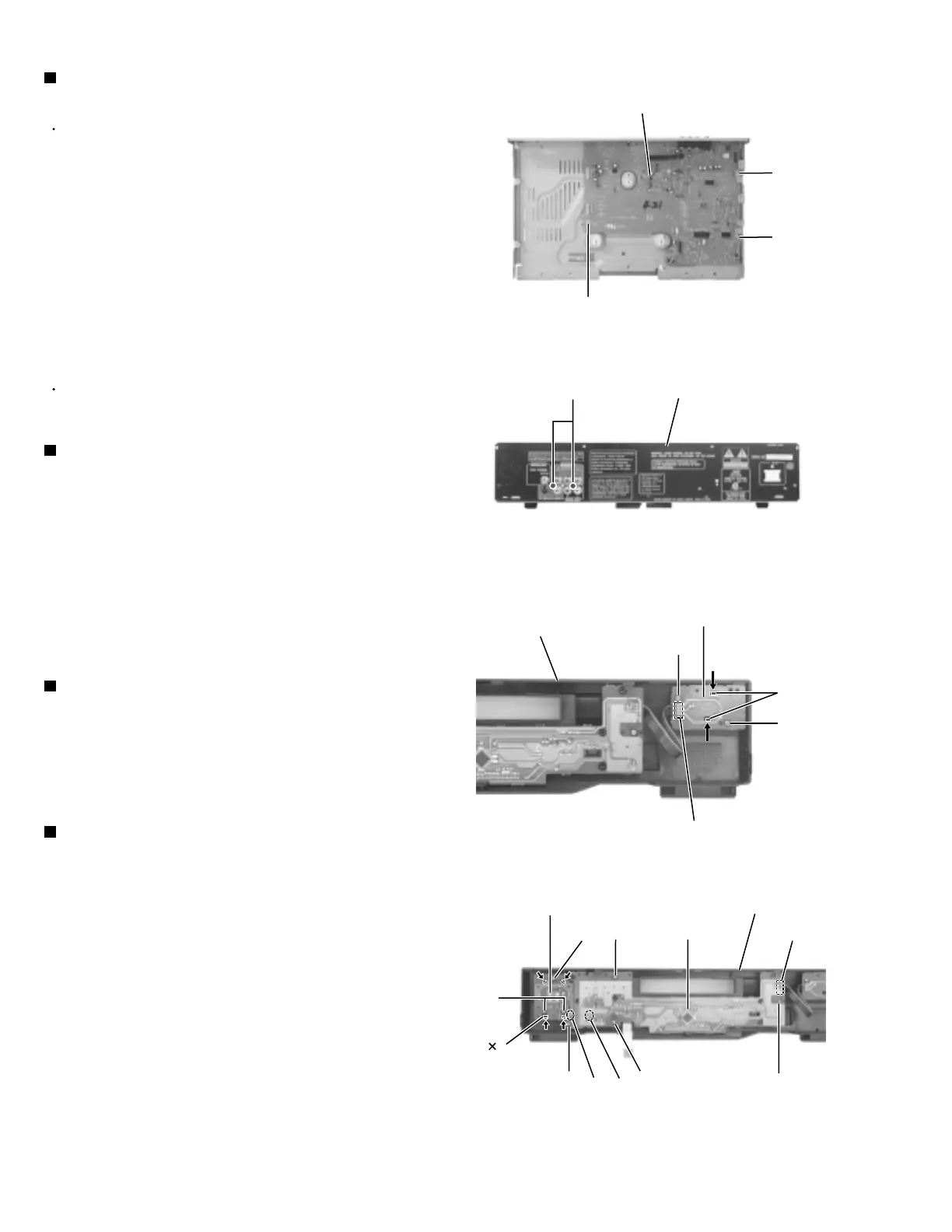
Prior to performing the following procedure, remove
the top cover, the front panel assembly, the DVD
mechanism assembly, the AC jack board and the
DVD Servo
.
Remove the three screws J attaching the main
board.
Remove the two screws C on the rear panel.
1.
2.
Removing the main board
(See Fig.19 and 20)
Unsolder connector FW841 on the power switch
board on the back of the front panel assembly.
Remove the two screws K attaching the power
switch board.
Push the two tabs g in the direction of the arrow and
remove the power switch board.
1.
2.
3.
Removing the power switch board
(See Fig.21)
Unsolder soldering i on the search switch board.
Remove the three screws M.
Release the four tabs j in the direction of the arrow
and remove the search switch board.
1.
2.
3.
Removing the search switch board
(See Fig.20)
Unsolder connector FW802 and soldering h on the
LCD board.
Remove the four screws L attaching the LCD board.
1.
2.
Removing the LCD board (See Fig.22)
Prior to performing the following procedure, remove
the top cover and the front panel assembly.
<Front panel assembly>
Fig.19
Fig.20
Fig.21
Fig.22
J
Main board
J
C
K
K
L
M
M
LLL
J
Rear panel
Power switch board
Front panel assembly
FW841
FW802
hi
Tabs j 4
Tabs g
Front panel assemblySearch switch board
LCD board
 Loading...