XV-N40BK,XV-N44SL
(No.A0040)1-7
SECTION 2
Disassembly method
2.1 Main body section
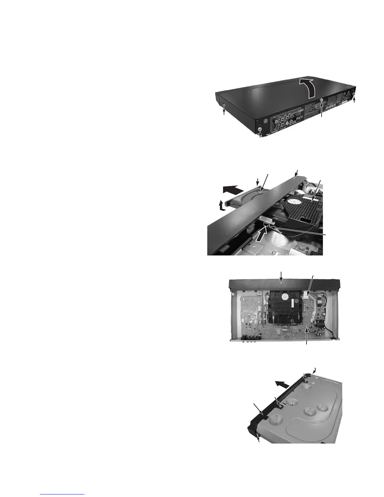
2.1.1 Removing the top cover (See Figure 1)
(1) Remove the two screws A attaching the top cover on both
sides of the main body.
(2) Remove the three screws B attaching the top cover on the
back of the main body.
(3) Raise the both sides and lower part of the rear of the top
cover, with opening them slightly in an outward direction.
And the top cover will be removed.
Fig.1
2.1.2 Removing the front panel assembly (See Figure 2, Figure 3, Figure 4)
• Prior to performing the following procedure, remove the top
cover.
• There is no need to remove the mechanism assembly.
(1) Insert a kind of screwdriver in a hole located in the right
side of mechanism assembly, and push a lever until it can-
not be inserted any further.
(2) And then, a tray will come out. Remove the tray in an upper
direction, with slightly opening the lower part of fitting in an
outward direction.
(3) Disconnect the card wire from connector CN901 on the
power supply board.
(4) Hook a and b are removed respectively, and the front panel
assembly is removed.
Fig.2
Fig.3
Fig.4
B
B
B
A x 2
TOP COVER
 Loading...