XV-N40BK,XV-N44SL
(No.A0040)1-9
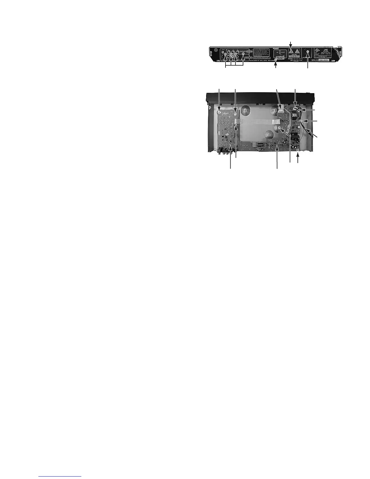
2.1.5 Removing the rear panel (See Figure 7, Figure 8)
• Prior to performing the following procedure, remove the top
cover.
(1) Remove the six screws E attaching the rear panel.
(2) Disconnect the power cord from connector P901 on the
power supply board
(3) Remove tie band.
Fig.7
Fig.8
2.1.6 Removing the output terminal board and power supply board. (See Figure 8)
• Prior to performing the following procedure, remove the top
cover/mechanism assembly/rear panel.
(1) Remove the two screws G attaching the output terminal
board.
(2) Disconnect the card wire from connector CN702 on the
output terminal board.
(3) Remove the three screws H attaching the power supply
board.
(4) Disconnect the card wire from connector CN901 on the
power supply board.
E E
Rear panel
E
CN901 P901
H
Tie band
Power cord
H
Power supply boardOutput terminal board
G G
CN702
H
 Loading...